
Ni-Cd Battery Automatic Charger
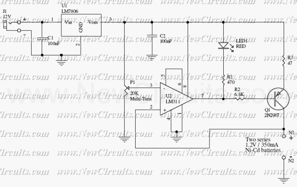
The circuit operates by utilizing an LM311 voltage comparator to monitor the charge state of two 350mAh "AAA" Ni-Cd batteries connected in series. The design includes a 20K Ohm multiturn potentiometer that allows for precise adjustment of the reference voltage at the third pin of the LM311. This reference voltage is set to 2.78V, which is critical for determining the charging threshold.
When the combined voltage of the two batteries reaches 2.81V, the output of the LM311 transitions to a high state. This transition is used to control a transistor that interrupts the charging current to the batteries, effectively stopping the charging process to prevent overcharging. The inclusion of a red LED serves as a visual indicator of the charging state; it illuminates when the batteries are being charged and turns off when the charging process has completed.
This circuit design is particularly advantageous for powering portable devices such as digital cameras, wireless headphones, and pocket radios, which typically require two "AAA" batteries. By employing rechargeable Ni-Cd batteries, users can significantly reduce operational costs and contribute to environmental sustainability through reduced battery waste. The automatic charging feature ensures that the batteries are charged efficiently and safely, enhancing the usability and longevity of the devices powered by this setup.The circuit presented in the above schematic has been designed to charge automatically two series 350mAh "AAA" size batteries. Set the 20KOhms multiturn potentiometer to get a 2.78V on the 3rd pin of the LM311 which is a comparator.
So if the net voltage of batteries reaches at 2.81V, the output of the LM311 goes high and then the state of the transistor becomes off, resulting in charging operation stops. When the red LED is lighted, it indicates that the charging is in the progress, and vice versa. To use portable devices such as digital camera, wireless headphone, pocket radio, etc, which they operates with two "AAA" size batteries, using rechargeable Ni-Cd batteries is a conscionable way to reduce cost. 🔗 External reference
Related Circuits
The usual chargers of battery automotive are simple and cheap appliances that charge continuously the battery with a rhythm of a few amperes for the time the appliance is ON. If the holder does not close the charger in...
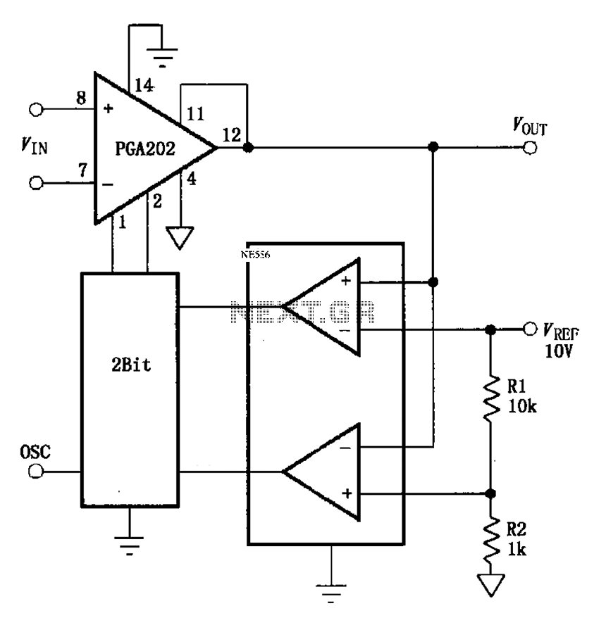
The automatic range switching circuit consists of PGA202, comparators, and counters, as illustrated in the figure. The comparator at the output compares VOUT with VREF. When VOUT exceeds 10V, the comparator generates a low signal, causing the up/down counter...
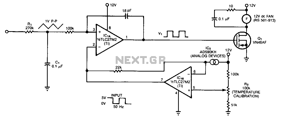
The controller circuit is designed to reduce a fan's noise, power consumption, and wear, especially when operating in low, fluctuating ambient temperatures. A temperature sensor is mounted in the fan's airstream, allowing the circuit to adjust the fan speed...
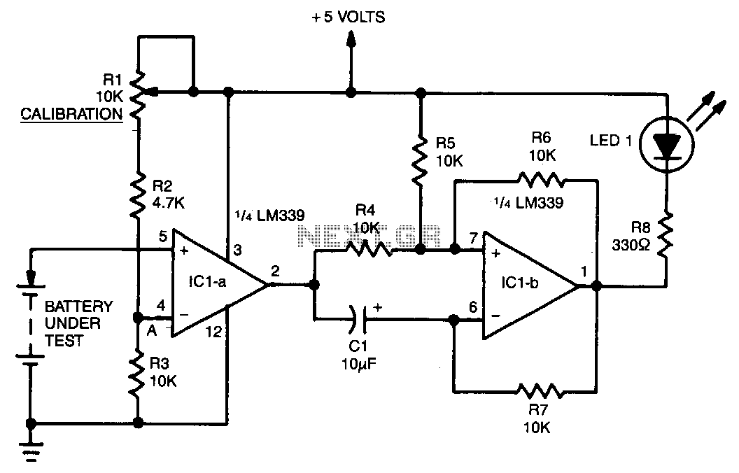
A voltage divider consisting of R1, R2, and R3 is utilized to establish the input reference voltage below which the batteries should be replaced. The reference voltage at point A is adjustable via R1. As illustrated in the diagram,...
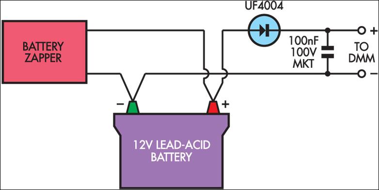
Several readers have inquired about how to determine when the Lead-Acid Battery Zapper has effectively completed the desulphation process. Based on the author's experience, batteries that are responsive to this treatment typically exhibit a notably high peak voltage across...

The phase and neutral wires from the power source have already been connected to electrical appliances such as fans and light points. According to the UPS connection diagram, an additional phase wire should be connected to those appliances where...