
Level led level meter display driver IC a circuit diagram
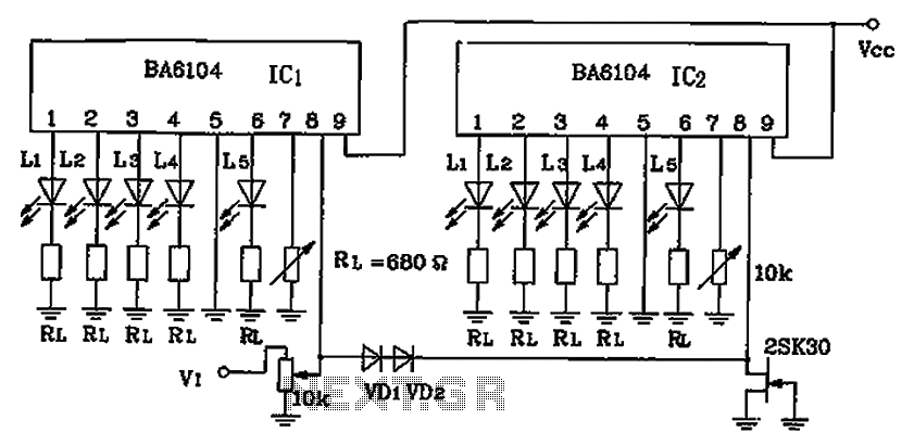
The BA6104 integrated circuit is designed for use in LED level meters, providing a visual representation of signal levels through a series of illuminated LEDs. The circuit typically consists of two sections, each controlling five LEDs, allowing for a total of ten LEDs to be utilized in a two-dot configuration.
In operation, the reference voltage (Vref) plays a crucial role in determining the brightness and activation of the LEDs. By adjusting the Vref at pin 7 of IC1, the corresponding LEDs (L1 to L5) can be set to illuminate fully, indicating a specific signal level. The same adjustment is made for IC2, which also controls its set of LEDs (L1 to L5). The design ensures that the output from IC2 is twice as bright as that from IC1, creating a clear distinction in visual feedback for users.
This dual configuration allows for effective monitoring of signal levels in various applications, such as audio equipment, where visual feedback is essential for performance assessment. The circuit design can be adapted for different voltage levels and LED configurations, making it versatile for various electronic projects. The BA6104 IC is particularly valuable for engineers looking to implement a straightforward yet effective LED level indication system in their designs. BA6104 Five-digit LED level meter level LED display driver IC circuit constituted as shown in FIG. BA6104 10 by two-dot LED level display circuit configuration shown in Figure adjusted Vref IC1 7 feet, so that IC1 in L1 ~ L5 5 pieces of LED full light; adjusting Vref IC2 7 feet of the IC2 of L1 ~ L5 5 pieces of LED full brightness, this light is 2 times IC1 voltage of the light-emitting order of L1 ~ L5 IC1 to IC2 of L1 ~ L5.
Related Circuits
When the ON/OFF button is pressed once, the equipment goes on and stays on. It goes off when the button is pressed again. The circuit is straightforward. It uses a JK CMOS Flip-Flop with its JK terminals tied high...

The digital circuit that is particularly useful is the One-Shot circuit, also known as a monostable multivibrator circuit. This circuit exhibits a specific behavior where it generates a single output pulse in response to an input trigger. The One-Shot circuit,...
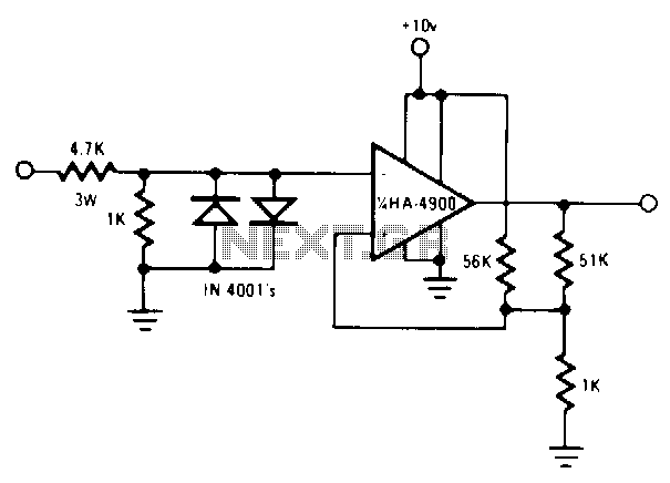
Utilize a pair of Maxim's 5V-powered MAX231 RS-232C transmitters as drivers to achieve a dual-color LED. These transmitters necessitate only a single-ended, 5-V input to internally generate ±10 V. Their outputs are designed to be short-circuit-proof and can provide...
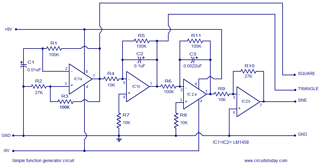
A simple function generator circuit utilizing the LM1458 is presented here. The LM1458 is a dual general-purpose operational amplifier. The two op-amps within the LM1458 share a common bias network and power supply line, yet operate independently. The function generator...
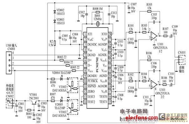
The peripheral circuit is straightforward, consisting of a DAC schematic circuit diagram for a USB interface that utilizes the PCM2702. The output of the circuit can be directly connected to a power amplifier and is capable of driving headphones...
The following circuit illustrates a 2500W Phase Control Circuit Schematic. Features include a ground-tied trigger output that is disabled, and a low voltage input. The 2500W Phase Control Circuit is designed to regulate the power delivered to a load by...