
Mobile Scanner Circuit
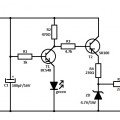
The circuit operates by harnessing the electromagnetic waves emitted by a mobile phone when it is in use. The sensor coil L is strategically placed to capture these RF signals. Upon detecting the RF emissions, the coil generates a small voltage that is amplified by the transistor T1. This amplification is crucial, as it ensures that the signals are strong enough to trigger the clock input of the CD4017 IC.
The CD4017 IC is designed to count the pulses received at its clock input. In this application, it functions as a signal processor that translates the RF pulses into control signals for the output devices. The outputs Q1 and Q2 are configured to drive an LED and a piezo buzzer, respectively. The LED provides a visual indication of the mobile phone's presence, while the piezo buzzer emits audible alerts, making the device effective even in environments with high ambient noise.
The resetting mechanism via output Q3 ensures that the activation cycle of the LED and buzzer is maintained. By resetting the IC every third pulse, the circuit prevents continuous activation, allowing for a more manageable indication system. The choice of using a ready-made inductor for the sensor coil simplifies the assembly process, while the small piezo buzzer is chosen for its compact size and efficiency in producing sound.
Overall, this RF detection circuit serves as a practical solution for locating mobile phones, especially in situations where traditional methods may fail due to silent modes or background noise. Its design emphasizes simplicity, efficiency, and effectiveness in providing both visual and auditory signals to the user.A device to locate the mobile phone. It emits intermittent flashes and beeps to indicate the presence of an active mobile phone. The circuit becomes active even if the mobile phone is in silent mode. It can be used to detect mobile phone call in noisy environments. Range of the circuit is 15 cm. The circuit is basically an RF detector. Dur ing the activation of mobile phone, strong RF field will be generated. The sensor coil L detects the RF signals and T1 amplifies the signals. The amplified signals are given to the clock input of IC1. CD 4017 is a Johnson decade counter IC with 10 outputs. Its clock input pin 14 is highly sensitive to RF pulses so that it is a very good choice for RF detection. Only two outputs (Q1 andQ2) of the IC are used while the Q3output is tied to the reset pin 15 so that IC will reset on every third pulse.
This will repeat the activation of LED and Buzzer. When the sensor detects the RF signal, clock input of IC1 gets pulses and its output pins 2 and 4 becomes high and low alternately giving flashing lights and beeps. The coil used in the circuit is a ready made inductor. Buzzer used is a small piezo buzzer. 🔗 External reference
Related Circuits
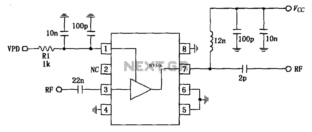
The circuit is based on an 880 MHz RF2347 low noise amplifier application. The radio frequency (RF) signal enters through input pin 3, and after amplification, the output is available at pin 7. The amplifier is directly coupled to...
This AC motor speed controller can handle most universal type (brushed) AC motors and other loads up to about 250W. It works in much the same way as a light dimmer circuit; by chopping part of the AC waveform...
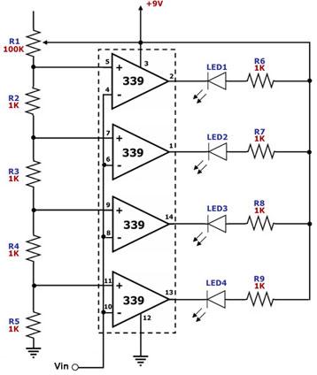
This circuit is designed as a simple LED bar graph voltmeter. Each operational amplifier in the LM339 quad package functions as a comparator, comparing the input voltage (Vin) to a series of fixed voltage levels that are proportional to...

The circuit of the easy-to-use LM3sDZ temperature detection system does not provide an adjusted output to obtain a 1 (hnV/°C) temperature change range if the temperature is between 0°C and a specified limit. The output voltage ranges from 0...
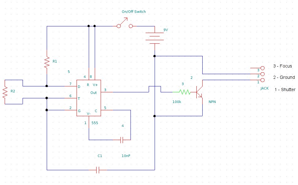
This document provides information on constructing a DIY time-lapse circuit that enables a camera to automatically capture images at specified time intervals. These images can then be compiled to create a time-lapse film. The circuit utilizes a 2.5 mm...
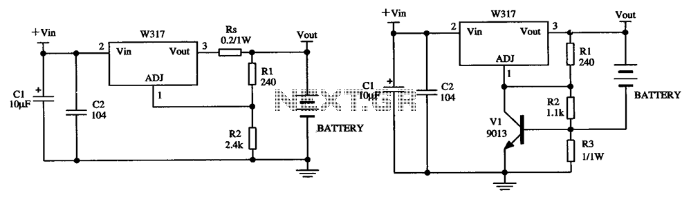
The W317 circuit integrates a three-terminal adjustable voltage regulator designed for battery charging applications. It features a constant pressure limiting charger circuit, where resistor Rs is employed to restrict the charge current, thereby reducing the initial charge rate. Additionally,...