
always on for pcs circuit

The described circuit serves as an effective solution for maintaining power to a PC in scenarios where uninterrupted operation is desired. It leverages a Schottky diode and a tantalum capacitor to create a mechanism that automatically restarts the system after a power failure or accidental shutdown. The choice of components is critical; the SB120 Schottky diode is selected for its low forward voltage drop and fast switching characteristics, which ensure that the circuit responds quickly to changes in power status. The 68 pF tantalum capacitor is utilized for its reliability and stability, providing adequate filtering to suppress voltage spikes and transients that could otherwise disrupt the operation of the circuit.
The integration of this circuit into the power supply system of a PC is straightforward, particularly when mounted on a 4-way Molex connector. This design not only simplifies installation but also enhances the durability of the components by providing a robust connection that can withstand regular usage. The heat shrink tubing serves as insulation, protecting the components from physical damage and preventing short circuits.
In practical applications, this circuit is particularly beneficial for systems that require high availability, such as servers or data acquisition systems. By ensuring that the PC can automatically restart after a power interruption, it minimizes downtime and allows for continuous operation. The ability to disable sleep modes or to use a compatible keyboard is essential for maintaining the functionality of the circuit, as any interruption in the power button signal can prevent the system from restarting.
The advanced version of the circuit, which retains the original power button functionality, provides an additional layer of control. This allows users to perform a controlled shutdown via the power button, ensuring that the operating system can save data and close applications properly before powering off. This feature is particularly important in environments where data integrity is crucial, as it helps to prevent data loss or corruption due to abrupt power loss.
Overall, the described circuit effectively addresses the need for reliable power management in PC applications, enhancing the versatility and resilience of personal computers in various operational contexts.Many enthusiasts will be using their PCs as data loggers, controllers or as web servers. ln these cases it is important that the machine is kept powered up for as great a fraction of the time as possible, even if there has been a power cut or if the power button is inadvertently pressed by another member of the household. Today`s operating systems offer a range of automation options and it is perfectly possible to arrange things so that the computer starts itself up automatically. The always on`circuit shown here automatically restarts an ATX PC in the above situations. There are just two components: a Schottky diode connecting the power but-ton pin on the motherboard to the +5 V line on the power supply, and a capacitor from the power button pin to ground.
The capacitor is a 68 pF tantalum type rated at 6. 3 V, and the diode is a type SB 120, rated at 20 V and 1 A. The total component cost is in the sub-one-beer range! The most convenient arrangement is to mount the circuit directly on a 4-way Molex disk drive power plug, insulating the capacitor and diode using heatshrink tubing. The assembly can then be plugged into a spare socket on the power supply. The operation of the circuit is straightforward. When the +5 V supply fails (i. e. , when the computer is turned off), the power button pin on the motherboard is pulled low via the Schottky diode.
This instructs the motherboard to power up again. As long as the +5 V supply is present, the diode blocks and the power button pin remains at high impedance, floating typically at around 3. 3 V. The capacitor serves to filter out spikes and brief dropouts. ln its simpler version the circuit replaces the power button on the case, and the computer can now only be switched on and off at the mains.
The author has tested the circuit on modern SuperMicro X8SAX and XSDTH-6F mother-boards as well as on an olderTyan Tiger MPX. He found that the capacitor value should be reduced in some cases: the SuperMicro motherboards have a high internal pull-up resistance which only charges the capacitor rather slowly.
Note that some PC keyboards have a Sleep` button which puts the computer into a low-power mode. ln this case the circuit will not work, and you should either use a keyboard without such a button or disable sleep modes from within the operating system. ln its more advanced version the existing power button is retained in parallel with the circuit (see circuit diagram).
The power button then causes a graceful shutdown` whereby the operating system can bring the computer to a halt in an orderly manner. 🔗 External reference
Related Circuits
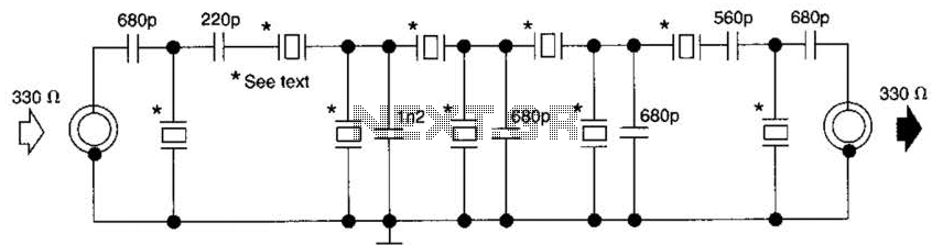
This filter utilizes five 455-kHz ceramic resonators. The impedance is 330 ohms, the bandwidth is 800 Hz, and the ultimate rejection is greater than 60 dB. Additionally, the ceramic resonators can be substituted with crystals. The described filter is a...

The timing circuit utilizes the 556 dual time base circuit, which includes an intermediate access N8281 crossover network. This design does not require a large volume capacitor, allowing for extended time delays. Initially, the first half of the 556...

A brief history: Like many tutorials, this one begins with a historical overview. However, it must be noted that there is limited background information available regarding the development of 7-segment displays. 7-segment displays are widely used electronic components that...
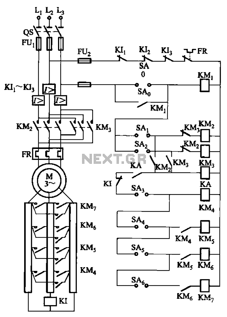
The circuit depicted in Figure 3-168 utilizes a controller for speed grading and reversing control. A reverse brake is connected to the rotor circuit through an overcurrent relay, labeled KI, for control. The current relay KIi to KI3 serves...

The circuit diagram presented below illustrates a portable gas detector. This device primarily utilizes electrochemical sensors and features dual-channel micro-power amplifiers, specifically the ADA4505-2. These amplifiers are configured in both a constant potential (U2-A) and a transconductance configuration (U2-B)....

The DC motor E inversion control circuit utilizes a loop configuration with various relay contacts. It employs a single set of normally open/normally closed relay contacts. When both inputs A and B are low, relay KI is activated. In...
Warning: include(partials/cookie-banner.php): Failed to open stream: Permission denied in /var/www/html/nextgr/view-circuit.php on line 713
Warning: include(): Failed opening 'partials/cookie-banner.php' for inclusion (include_path='.:/usr/share/php') in /var/www/html/nextgr/view-circuit.php on line 713