
4h 556 composed of a timing circuit diagram
The described timing circuit leverages the 556 dual timer integrated circuit, which consists of two independent timer sections that can be configured in various modes, including monostable and astable operation. In this configuration, the first half of the 556 timer is set up in astable mode, functioning as an oscillator. The frequency of oscillation is determined by external resistors and capacitors connected to the timer, forming a time period of T = 1.1RC for monostable operation. In the case of astable operation, the output waveform frequency can be calculated using the formula f = 1.44 / (R1 + 2R2)C.
The output from the first half of the 556 timer is directed to an N divider network. This divider effectively reduces the frequency of the incoming signal by a factor of N, generating a new output signal with a frequency of f/N. This output is then used to trigger the second half of the 556 timer, which can also be configured in monostable mode to produce a defined delay. The total delay produced by the circuit can be adjusted by varying the values of the external components connected to the second half of the 556 timer, allowing for time delays ranging from 30 minutes to 4 hours.
For applications requiring longer delays, the integration of an N8281 divider allows for further expansion of the timing capabilities. This additional divider can be cascaded with the existing circuit, enabling the overall delay to extend to several days or even weeks. This flexibility makes the timing circuit suitable for various applications, including automated control systems, timers for events, and other scenarios where precise timing is essential.
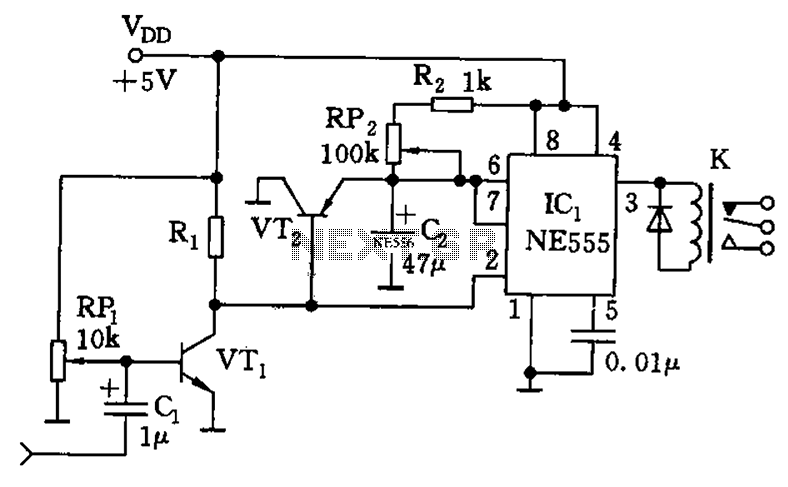
The schematic representation of this circuit would include the 556 dual timer IC, resistors, capacitors, and the N8281 divider, clearly indicating the connections and configurations necessary to achieve the desired timing functions. Proper labeling of component values and settings would facilitate understanding and implementation in practical applications. As shown by the timing circuit 4h is up to 556 pairs of the time base circuit. 556 dual time base circuit intermediate access N8281 crossover network, without having to use a l arge volume capacitor, it can get quite a long time delay. First l/2 (556) in the oscillator mode, with a period l/f. The oscillator output is applied to the N divider network to produce an output signal having N/f cycles used to trigger other half 1/2 (556). The divider is connected to a second half (556) of the input feet, it determines the total amount of delay produced by the divider.
Delay time has 30min, 1h, 2h, 4h, 4 block. If an additional series N8281 divider, such that the total amount of delay can be increased up to several days or even weeks.
Related Circuits
Powered by a solar panel, the circuit provides a 5V pure regulated DC voltage. It consists of an oscillator transistor and a regulator transistor. The solar panel charges the battery when sunlight is sufficient to generate a voltage above...
There are at least three different versions of this circuit. The first DM-2 version utilized the MN3005 BBD and the MN3101 Clock Driver IC (PCB marking: ET5214-510). Later, the clock driver was changed to the MN3102, and the BBD...
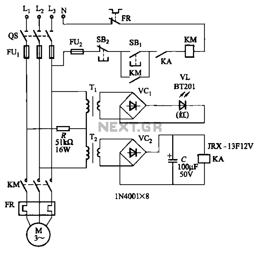
The circuit depicted in Figure 3-92 employs a dual-phase sequence protection relay for sensing. When the power supply exhibits a positive phase sequence (U, V, W), the relay KA is activated. If the power supply maintains the correct phase...
A capacitance meter is an essential instrument for electronics hobbyists and professional electronic technicians. A capacitance meter is a specialized device designed to measure the capacitance of capacitors in various electronic circuits. It typically features a digital or analog display...
The AP500A amplifier offers numerous advantages, providing unmatched superiority in stereo applications. It can utilize various amplifier configurations, including OTI, CI, rK, BTL, class AB, and super CP. The typical DC amplifier module for the AP500A is illustrated in...
Pump prime connector, power distribution cell, fuel pump and sender, dual tanks, fuel pump balance relay, vehicle control module, underhood fuse relay, ECM fuse. The described components are integral to the operation and management of a fuel system in a...