
simple mixer schematic

This circuit can be utilized in various audio applications due to its versatility and simplicity. The operational amplifiers serve as the core components for mixing, providing the necessary amplification and signal processing. The gain control is facilitated through the use of linear potentiometers, allowing for precise adjustments to the mix levels of each input. The switchable high/low sensitivity feature enhances the circuit's adaptability to different audio sources, ensuring optimal performance whether dealing with low-level microphone signals or higher-level effects outputs.
The component selection is crucial for achieving the desired performance characteristics. The resistors are chosen to set the input impedance and gain levels appropriately. For instance, the use of 180K ohm resistors helps maintain a high input impedance, which is beneficial for connecting various audio sources without loading them down. The 2.2M ohm resistors contribute to the overall gain settings, while the lower-value resistors (750 ohm, 1K, etc.) are essential for establishing feedback and stability within the op-amp circuits.
In practical applications, this mixer can be used in small recording studios, live sound setups, or as part of a larger audio processing chain. Its ability to handle multiple inputs and provide a clean mix makes it a valuable tool for audio engineers and hobbyists alike. Furthermore, as the circuit is designed for easy replication, it allows for scalability in projects requiring additional input channels.
For those interested in circuit assembly, the provided schematic diagram will guide the layout and connections of all components, ensuring a coherent and functional mixer. Proper attention to component orientation, particularly for the op-amps and transistors, is essential to avoid circuit malfunction. Overall, this mixer circuit exemplifies an efficient and effective solution for audio mixing needs.Here the simple mixer with 4 input and 2 op-amps: A basic mixer suitable for mixing microphones or even effects outputs. The overall gain from input to output is one if the pot related towards the input is full up. You can make this a net gain of ten (or any other reasonable gain) by. Simple and cheap mixer circuit. This circuit supplied using 9V power supply. There is high/low-sensitivity switchable inputs for each input channel. Component part list: P1, P2, P3_5K Linear Potentiometers R1, R11, R15_180K 1/4W Resistors R2, R12, R16_2M2 1/4W Resistors R3, R13, R17_750R 1/4W Resistors (See Notes) R4, R14, R18_1K 1/4W Resistors R5_15K 1/4W Resistor R6_220R 1/4W Resistor R7_1K5 1/4W Resistor R8_820R 1/4W Resistor R9_150R 1/4W. This is audio mixer circuit. The circuit is for one channel input, if you need, for example 5 channel mixer, then you need to build 5 similar circuits.
Schematic diagram: Component part list: TR1, 2 = FCS9015 ; TR3 = C1213 ; IC1, 2 = 741 or TL071 The kit of this circuit is available on the. Here`s a very simple circuit inverter that converts DC current into AC current, from 12V DC to 220V AC with output power of 5W.
Inverter circuit is typically used for emergency lighting, since the power output is small, which is about 5W only. But you can use this inverter for other purposes that do not. Above schematic diagram is a small 325mW amplifier circuit based on LM386 with a voltage gain of 200 that can be used as a bench amplifier, signal tracer or used to amplify the output from personal radios, MP3 players, MP4 Players or iPods.
How this circuit works: The gain of the LM386 can be controlled. The following circuit is a simple fire alarm circuit based NE555 timer and use thermistor as a temperature detector. This sensor will activate the transistor when the temperature is in high value. The thermistor will have a low resistance at high temperature, while at low temperature, the transistor resistance is high.
This characteristic of thermitor. 🔗 External reference
Related Circuits

A simple lab power supply electronic project can be designed using this circuit diagram, which is based on the LM2576 monolithic integrated regulator that provides all the active functions for a step-down (buck) switching regulator. As seen in the...

The circuit has four inputs. The voltage gain between each input and the output is maintained at unity by the relative values of the 470 kΩ input resistor and the 470 kΩ feedback resistor. The described circuit operates as a...
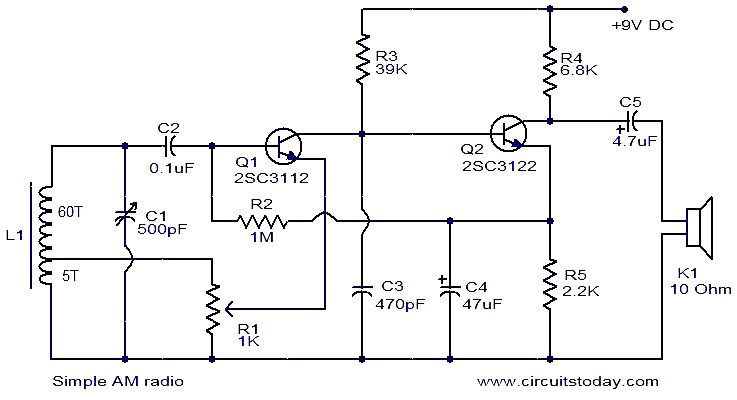
This is a straightforward AM radio circuit utilizing only two transistors. The coil L1 and variable capacitor C1 create the tank circuit. Transistor Q1 is responsible for demodulation, and the demodulated signal is accessible at the base of Q1....
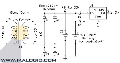
This circuit supplies electric power from a backup battery when AC power is interrupted, ensuring a stable 5V power supply for sensitive devices such as microcontrollers and logic circuits. The capacitor C1 should have a capacitance greater than 220...
When the unit is positioned near a live conductor, whether insulated or buried in plaster, capacitive coupling occurs between the live conductor and the probe. This interaction activates the counter, resulting in the LED flashing five times per second,...
The Boss SD-1 Super OverDrive is a pedal characterized by a straightforward design, incorporating a dual operational amplifier (uPC4558C) and six transistors, along with an asymmetric overdrive circuitry that emulates the classic, natural growl of a tube amplifier. It...