
Long-range high-frequency transistor FM transmitter circuit diagram
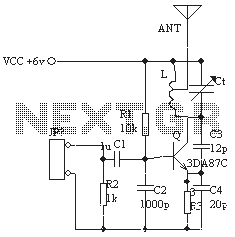
The circuit design employs the 3DA87C triode configured as a three-point oscillator, which is essential for generating the FM signal. The oscillator's operation relies on precise component values to ensure the output frequency falls within the FM band. The transistor's gain is a critical parameter, as it amplifies the oscillation signal, thus enhancing the transmitter's range. The choice of high-frequency ceramic capacitors is paramount to minimize losses at the operating frequencies and ensure stability in the circuit.
The inductor's configuration, with its specific number of turns and dimensions, plays a significant role in determining the resonant frequency of the oscillator. The center tap facilitates the connection to the antenna, which should be matched in length to optimize the radiation pattern and transmission efficiency. The use of a high-frequency transistor such as the C3355 significantly improves the circuit's performance, allowing it to operate effectively within the desired frequency range.
Finally, the circuit must be tested and tuned meticulously to achieve the best performance. This includes adjusting the variable capacitor and ensuring all connections are secure to minimize signal loss. The assembly should be housed in a suitable enclosure to protect the components and reduce interference from external sources. Following these guidelines will yield a reliable long-range FM transmitter capable of operating effectively within the FM spectrum.As shown in FIG ordinary triode 3DA87C to make long-range FM transmitter circuit, which is normal three-point oscillator circuit, the remote transmitter circuit with large current emissions, in open areas up to 1KM, according to the schematic assembly tests, the transistor magnification to choose flag with a blue dot is greater than 80 times, but found it not fall within 88-108MHZ normal frequency of the FM band, but no matter how to adjust the capacitance and inductance in the experiment, were lower than the 88MHZ about 25 percent more than a dozen MHZ frequency point, radio with TV audio reception function TESUN radio to function properly received, fT cutoff frequency parameter value of the transistor is not enough, not to mention its oscillation frequency to go up. In order to increase the distance between transmitter and receiver can change its frequency falls within the range of normal FM radio, had to look for another high-frequency transistor with D40, C1971, C1972, or as a high frequency oscillation power amplifier circuit, with its high-power output to increase the transmission distance, but such high-frequency transistor market is difficult to buy, and even buy, most of these fakes can not be used.
Later found with the C3355, this transistor cutoff frequency of several thousand MHZ, its power of 600MW, is sufficient for the FM band, then the circuit will make some improvements, can easily produce a long-range FM transmitter circuit. Select components: capacitors C2, C3, C4 are high frequency ceramic capacitors, Ct is 5 / 25P high-frequency semi-adjustable capacitor to be replaced with high-frequency ceramic value after completion of debugging test with a digital multimeter capacitance, L is a diameter of about 6 turns bodiless 8mm 0.9 enameled wire on the pipe, then opened about 2CM, center tap, using a TV antenna or a transmitting antenna in place with the same length of wire.
Actual debugging to the best of its transmission power maximum distance of not less than 500 meters.
Related Circuits
The PIC16C57-RCT is a communication single-chip microcomputer integrated circuit that is commonly utilized in the Qiao Xing series of IC card management telephones. The PIC16C57-RC integrated circuit features a pulse and dual-tone dialing circuit, memory data and clock circuit,...
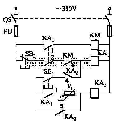
Competition among relay contacts in contactor control systems often leads to significant issues that can be cumbersome to address. In some cases, this requires the addition of numerous components. However, utilizing a negative temperature coefficient thermistor (NTC) for delay...
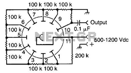
This circuit is representative of the typical application of a photomultiplier tube. The circuit depicted is AC coupled; however, if DC coupling is required, the capacitor can be removed, and an appropriate interfacing method should be employed. A common...
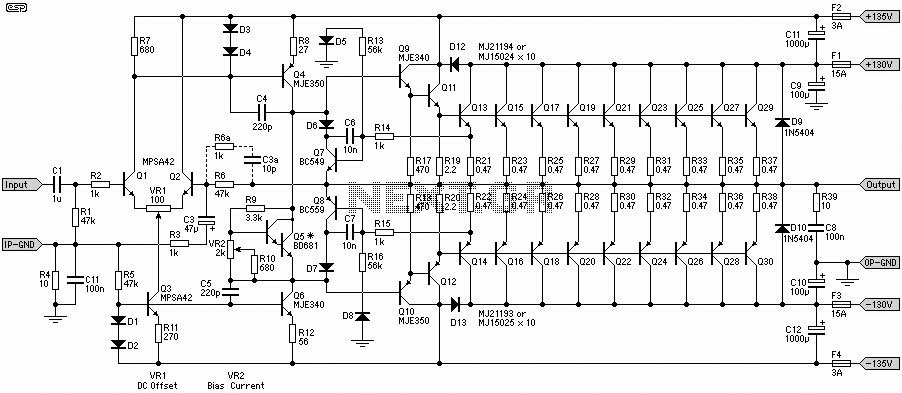
This 1500W Power Amplifier Circuit Diagram contains two images of the circuit. For more complete information, refer to the main post titled "1500 Watt Power Amplifier." It includes a list of component parts for the 1500W Power Amplifier Circuit...
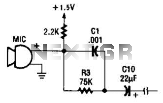
This circuit is suitable for using an electret microphone for various applications. A 1.5-V battery is utilized. CI and R3 provide treble boost and bass cut; they can be eliminated if desired. The described circuit employs an electret microphone, which...
This is a useful instrument for workshops. The standard of the produced frequencies is 10 to 1. The basic frequency is produced by a crystal with high accuracy. The circuit consists of the oscillator, around the crystal and the...