
fm tracking transmitter circuit

The tracking transmitter circuit operates effectively in the FM band by utilizing a combination of a 555 timer IC and JFETs to achieve frequency modulation of audio signals. The 555 timer, known for its versatility in generating precise timing and oscillation, is configured to produce an audio tone at a specific frequency. The JFETs are key components that facilitate the modulation and transmission of this audio signal.
In the circuit, the first JFET, Q1, is configured as a Hartley oscillator. This configuration allows for the generation of a stable oscillating signal, which is modulated by the audio tone input. The modulation occurs as the audio signal influences the frequency of the oscillator. The second JFET, Q2, serves as a buffer, providing isolation between the oscillator and the transmitting antenna. This isolation is critical to prevent loading effects that could distort the oscillator's output frequency.
The diode D1, acting as a varactor, plays a significant role in tuning the oscillator's frequency. By applying a reverse bias voltage, the capacitance of the diode changes, which in turn affects the frequency of the oscillator. This mechanism allows for dynamic frequency modulation, enabling the circuit to transmit audio tones effectively over a distance of up to 100 meters.
The inductor L1 is essential for the oscillator's operation and is constructed from 18 SWG enameled copper wire. The specific winding configuration, including the center tap, is designed to optimize the inductance and improve the performance of the oscillator. The antenna, a simple 20 cm wire, is utilized to radiate the modulated signal into the surrounding environment, facilitating effective transmission.
Overall, this circuit design exemplifies a straightforward yet effective approach to creating a tracking transmitter for audio tones within the FM band, making it suitable for various applications such as remote control systems and signal transmission.This is a design for the tracking transmitter of audio tone in FM band frequency. The circuit can be used a signal transmitter or remote control transmitter. The circuit is use only the available components. The range of the transmitter is 100 m in the distance using 9V power supply and with a matching antenna. The circuit is built by 555 timer IC for producing the audio tone and based on JFET as core the circuit. This is figure the circuit. The operation of the circuit is the first JFET (Q1) is wired as a Hartley oscillator which is frequency modulated by the audio tone. The second (Q2) JFET is wired as a buffer to isolate the oscillator based on Q1 from the antenna. The diode D1 is used as a varactor here. The diode is reverse biased by the ramping voltage produced at the pin 6&2 of the IC1. This results in the change of junction capacitance of reverse biased diode, which in turn alters the frequency of the oscillator to attain the frequency modulation.
The inductor L1 can be made by winding 5 turns of 18 SWG enameled copper wire on a 3/8 inch long, 3/16 inch diameter plastic tube. The coil must be tapped at the center. The antenna can be a 20cm long wire. 🔗 External reference
Related Circuits
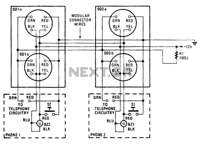
An intercom utilizing dual-modular wall jacks is depicted in this circuit. If the wires are accessible in the home telephone cable, this system can be installed with minimal difficulty. The intercom system described employs dual-modular wall jacks, which are standard...
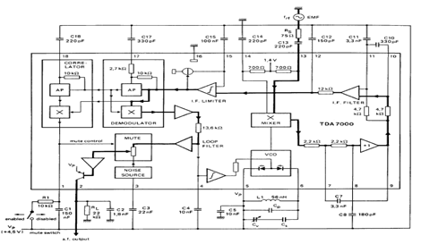
The TDA7000 is an integrated circuit (IC) designed for FM portable radios, featuring a Frequency-Locked Loop (FLL) system with an intermediate frequency of 70 kHz. It incorporates several functions, including an RF input stage, mixer, local oscillator, IF demodulator,...

The EUA2032 is a high-efficiency, 2.5W mono class-D audio power amplifier. A newly developed filterless PWM modulation architecture further reduces EMI and THD+N, as well as eliminates the LC output filter, thereby reducing the external component count, system cost,...
This circuit diagram for a 12V inverter is straightforward to construct, utilizing inexpensive components that many electronics hobbyists may already possess. While it is feasible to design a more powerful circuit, the complexity associated with handling high currents on...
A simple square wave oscillator can be created using two gates from a CMOS 4011 NAND chip. Alternatively, a CMOS 4001 chip or a TTL equivalent can also be utilized. In this circuit, the mark-space ratio can be independently...
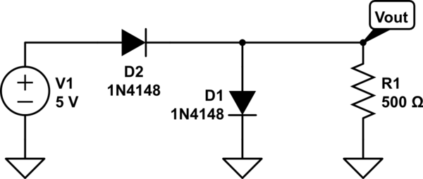
The two diodes will fail. It is advisable to include series resistors for them. If the simulation is successful, the current through the diodes will be excessive. Both diodes do not necessarily need to fail; one may become a...