
am dsb transmitter for hams
The AM transmitter circuit operates by utilizing several key components that work together to produce a modulated signal suitable for transmission. The Op Amp IC741 serves as the initial stage, amplifying audio signals picked up by the condenser microphone. This processed audio signal is then sent to the double balanced modulator, which plays a crucial role in creating the desired DSBSC output. The modulator consists of four IN4148 diodes arranged to effectively suppress the carrier frequency while allowing the sidebands to pass through.
The carrier frequency is generated through a crystal oscillator, which ensures stability and precision in the transmission frequency. The BC548 transistor is responsible for generating this carrier, while the T1 transistor amplifies the signal and buffers it before it reaches the modulator. The use of a selector switch allows for easy frequency adjustments by swapping out crystals, providing versatility in operation.
To manage the carrier leakage that may occur due to diode mismatching, precise adjustments can be made using the VR2 and C7 components. This feature is particularly useful for ensuring that the transmitter can still be received by standard AM radios, should the user choose to operate in that mode.
The RF amplification stage is critical for boosting the modulated signal to a level suitable for transmission. The 2N2222A transistor serves as a pre-amplifier, effectively increasing the signal strength before it is sent to the final power amplifier, which uses the SL100B transistor. Proper thermal management is essential for the SL100B to ensure reliable operation during extended use.
The choice of antenna significantly influences the transmission range and quality. The horizontal dipole antenna is favored for its simplicity and effectiveness, especially at the specified frequency of 7 MHz. The use of a 75-ohm coaxial cable for the antenna connection further enhances signal integrity. Overall, the design of this AM transmitter circuit emphasizes efficiency and adaptability, making it suitable for various amateur radio applications.The circuit of AM transmitter is designed to transmit (amplitude modulated) DSB (double side band) signals. A modulated AM signal consists of a carrier and two symetrically spaced side bands. The two side bands have the same amplitude and carry the same information. In fact, the carrier itself coveys or carries no information. In a 100% modulated
AM signal 2/3 rd of the power is wasted in the carrier and only 1/6th of the power is contained in each side band. In this transmitter we remove the carrier and transmitt only the two side bands. The effective output of the circuit is three times that of an equivalent AM transmitter. Op Amp IC741 is used here as a microphone amplifier to amplify the voice picked up by the condenser microphone.
The output of the op amp is fed to the double balanced modulator (DBM) build around four IN4148 diodes. The modulation level can be adjusted with the help of preset VR1. The carrier is generated using crystal oscillator wired around BC548 transistor T2. The carrier is further amplified by transistor T1, which also acts as a buffer between carrier oscillator and the balanced modulator.
The working frequency of the transmitter can be changed by using crystals of different frequencies. For multi frequency operation, selection of different crystals can be made using a selector switch. Ths output of the DBM contains only the product (of audio and carrier) frequencies. The DBM suppresses both the input signals and produces double side band suppressed carrier (DSBSC) at its output. However, since the diodes used in the balanced modulator are not fully matched, the output of the DBM does contain some residual carrier.
This is known as carrier leakage. By adjusting the 100 ohm preset VR2 and trimmer C7 you can null the carrier leakage. To receive DSB signals you need a beat frequency oscillator to reinsert the missing carrier. If you don`t have a beat frequency oscillator, or want to transmitt only AM signal, adjust preset VR2 to leak some carrier so that you can receive the signals on any ordinary radio receiver. In AM mode 100% modulation can be attained by adjusting preset VR1 and VR2. The DSBSC signal available at the output of the balanced modulator is amplified by two stages of RF linear amplifiers.
Transistor 2N2222A (T3) is used as an RF pre amplifier, which provides enough signal amplification to drive the final power amplifier build around transistor SL100B. The output of the final power amplifier is connected to the antenna. All coils are to be wound ferrite balun core (same as used in TV balun transformer of size 1. 4 cm * 0. 6 cm) using 24 swg enameled copper wire. Proper heat sink should be provided for SL100B transistor used as final power amplifier. Range of the circuit depends on the type of antenna used. It is very important to use matched antenna to radiate the signals effectively. I used horizontal dipole antenna, which is simple and easy to construct. For 7 MHz, ie 40 meter ham band the length of dipole antenna will be 20 meter. Use 75 Ohms co-axial cable to connect antenna and transmitter. I was able to get 57 report from station 80 kilometer away. You can easily add a Linear RF amplifier using IRF830 to get more power.
Related Circuits
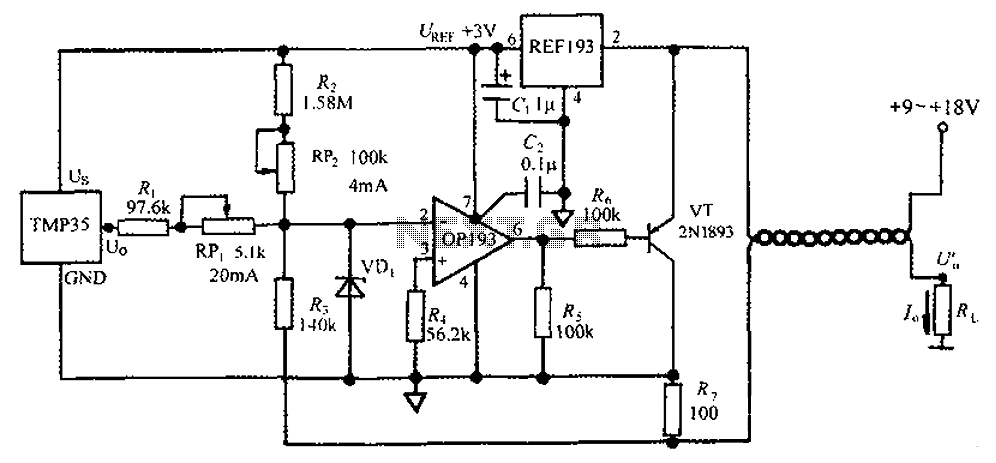
The circuit consists of a TMP35 temperature transmitter that converts a voltage signal output from the TMP35 into a standard 4 to 20 mA current signal. This configuration is suitable for use in automated instrumentation and industrial temperature control...
This transmitter needs heatsink at 2N2219. With the C4 we regulate the frequency. With their C7, C8 we adapt the resistance of aerial (practically to them we regulate so that it is heard our voice in the radio as...

The following circuit is a power amplifier circuit for an FM transmitter with an output power of 30 watts. The power amplifier circuit utilizes a power transistor of type 2SC1946A. The FM transmitter operates with a 13.8-volt DC power...
This is a simple design of a small FM transmitter bug that is ideal for transmitting and eavesdropping purposes. Due to its high sensitivity, it can even pick up the ticking of a clock. The estimated range is approximately...

The LV2283VB is an FM Transmitter Integrated Circuit (IC). The multiplex (MPX) block generates a stereo modulated composite signal from left and right audio inputs. The RF Voltage-Controlled Oscillator (VCO) incorporates the FM modulation function. The Phase-Locked Loop (PLL)...
This wireless headphone transmitter ensures a reliable connection over a distance of 2 meters. The oscillator frequency ranges between 1750 KHz and 3500 KHz, utilizing a ferrite bar as the antenna. IC1 amplifies the audio signal, while TC1 serves...
Warning: include(partials/cookie-banner.php): Failed to open stream: Permission denied in /var/www/html/nextgr/view-circuit.php on line 713
Warning: include(): Failed opening 'partials/cookie-banner.php' for inclusion (include_path='.:/usr/share/php') in /var/www/html/nextgr/view-circuit.php on line 713