
AM/FM Granco 720 radio circuit
The Granco 720 model was produced by Granco Products, Inc. around 1955. Founded post-World War II by Seymour Nepolin, the company was based in Long Island City, New York, and engaged in research related to FM, UHF receivers and tuners, stereophonics, multiplexing, high fidelity, MF car receivers, and electronic air purifiers. The 720 model followed previous models such as the CTU, LCU, MTU, and 610. The initial three models served as UHF converters, while the 610 model was Granco's first FM-only radio. Granco primarily manufactured devices using plastic, and the 610 model shares similarities with the 720 model in terms of chassis design, tube placements, and plastic casing. The company played a significant role in making affordable, compact FM radios widely available. In 1959, a fire at the Granco facilities led to the company's decline following complications with insurance settlements. This incident was ignited by a high-wattage soldering iron that caught a wooden bench and adjacent stockroom ablaze. In 1960, Emerson Radio negotiated an option to purchase shares in Granco for operational funding. Emerson Radio's president, Benjamin Abrahms, noted the growing interest in FM, highlighting the increasing sales of FM sets and Granco's leadership in the market. Emerson Radio eventually sold its Granco shares in 1963 and began producing its own FM radios. On April 23, 1963, Granco filed for bankruptcy, reporting liabilities of $640,543 against assets of $362,982. Years later, Granco's founder established the Melsey Corporation to develop VHF and UHF oscillators and a grid-dip meter.
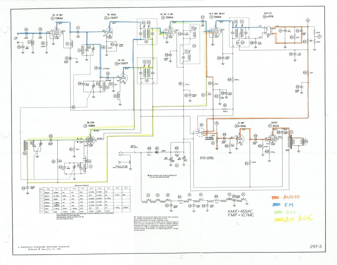
The Granco 720 operates through a series of stages, utilizing seven vacuum tubes of five different types. Each tube's specific function is crucial for the overall operation of the radio. A detailed table outlines the main features of these tubes, while another table presents the wiring and grid names, aiding in the interpretation of the overall schematic. As a low-cost AM/FM receiver, the FM section employs an internal and AC wire antenna, contributing to the radio's performance and reception capabilities. The careful evaluation of each component and stage in the Granco 720 enhances the understanding of vintage radio technology and its relevance to contemporary electronic design principles.This post documents the restoration of an antique AM/FM Granco 720 radio. It examines the design of the AM and the FM receiver. It details the alignment of the receivers, discusses repairs and evaluates the performance of the radio. Restoration of antique radios has a niche in the electrical engineering community. Engineering students, such as the author, become interested in the topic to learn about the history of their chosen profession and to learn RF concepts also found in modern circuits.
It is an opportunity to learn from the masters and to study the innovation of our historic predecessors. The purpose of this paper is to detail the restoration of a Granco 720 antique radio. It describes the radio, starting from the vacuum tubes up to the circuitry of the AM and the FM receiver.
It describes the steps taken to make the radio electrically safer, repair detected problems, and alignment of the receiver. Also, we describe measurements taken to evaluate leakage of capacitors, expected DC bias voltages and the audio frequency response.
Finally, we present a list errors and accidents that happened during restoration and how we fixed them. The Granco 720 radio is a compact 7. 5 x 5. 1 x 5. 5 inch molded plastic table top AM/FM set. It is an AC/DC super heterodyne set that works with 117V. It has 7 tubes, a slug tuner for FM and a tuning capacitor for AM. The audio output uses permanent magnet 4G—6 inch loudspeaker with a moving coil [1]. The Granco 720 model was manufactured by Granco Products, Inc circa 1955. This company was founded after World War II by Seymour Nepolin [2]. Granco Products, Inc was located 36-17 20th Avenue, Long Island City, New York. The company`s research included FM, UHF, receivers and tuners, stereophonics, multiplexing, high fidelity, MF car receivers and electronic air purifiers [3] [4]. The 720 model followed the models CTU, LCU, MTU and 610. The first three models were UHF converters. The 610 model was an FM-only radio, the first radio of the company. Granco manufactured most of its devices in plastic, and the 610 model greatly reassembles the 720 model.
It uses a similar chassis, tube locations, and the same plastic covering. Granco contributed to bring affordable and small FM radios to the mass market. In 1959, a fire hit the Granco facilities and the company disappeared after troubles with the insurance settlement. This fire was started when a high wattage soldering iron ignited a wood bench and the stockroom with plastic cabinets next door.
After the fire, in 1960, Emerson Radio agreed for option to buy shares in Granco to provide working capital. According to the Benjamin Abrahms, president of Emerson Radio, FM has become increasingly interesting to us [noting] that the sales of FM sets has been on the rise and that Granco is a leading producer of such sets .
Emerson Radio became the exclusive marketing agent for Granco. In 1963 Emerson Radio sold its Granco shares and started manufacturing its own FM radios. On April 23, 1963, Granco filed for bankruptcy claiming liabilities of $640, 543 and assets of $362, 982. Years later, the founder of Granco started the Melsey Corporation to develop VHF and UHF oscillators and a grid-dip meter [3].
This section describes how the Granco 720 works. First, we describe the characteristics of the tubes found in the radio. Then, we overview the stages involved in the radio operation. Third, we look into the details of how each stage works. The Granco 720 radio uses seven vacuum tubes of five different types. In this section, we describe the specifics of what each tube is designed to do. Table 1 describes the main features of the tubes. Table 2 shows the wiring and grid names. This will be useful when we study the schematic as a whole and interpret the circuit. The Granco 720 radio is a low cost AM/FM receiver. From a high level, the FM receiver uses a internal and AC wire antenna, an FM radio f 🔗 External reference
Related Circuits
The schematic illustrates a 12 W Bridge Amplifier circuit diagram utilizing the TDA2007A, a class AB dual audio power amplifier. This amplifier is specifically designed for stereo applications in music centers, television receivers, and portable radios. As stated in...
This is a simple LED-powered audio amplifier circuit utilizing a MOSFET amplifier with the TL071C operational amplifier. It can deliver up to 45 W into an 8-ohm load. The circuit incorporates the MOSFETs IRFP240 and IRFP9240, which are recommended...
A passive light-emitting diode output level indication circuit. This circuit utilizes a light-emitting diode (LED) to provide a visual indication of the output level from a given source. The design is characterized by its passive nature, meaning it does not...
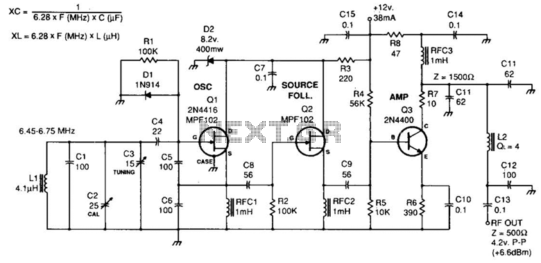
Fixed-value capacitors are disc ceramics. C1, C4, C5, C6, and C8 are NPO ceramic or polystyrene. C2 is a 25-pF ceramic trimmer and C3 is a 15-pF miniature air variable capacitor. The resistors are ¼ watt carbon film or...

The circuit expands a single 15-pin D-sub VGA output to multiple outputs, allowing for the connection of up to six monitors simultaneously. The input VGA connector is positioned on the left side, while the six output VGA connectors are...
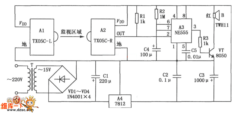
The TX05C-R infrared surveillance alarm circuit is designed for monitoring walls, windows, doors, and various restricted areas. When an intrusion occurs, the alarm activates to enhance security. The circuit comprises a transmitter module, a receiver module, a time-base circuit,...
Warning: include(partials/cookie-banner.php): Failed to open stream: Permission denied in /var/www/html/nextgr/view-circuit.php on line 713
Warning: include(): Failed opening 'partials/cookie-banner.php' for inclusion (include_path='.:/usr/share/php') in /var/www/html/nextgr/view-circuit.php on line 713