
AM radio circuit for electronics project
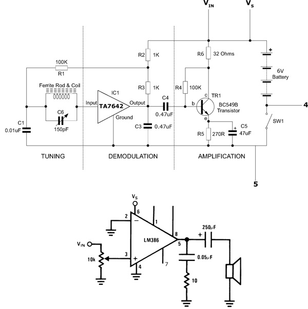
The radio circuit design incorporates several key components to achieve its functionality. The power supply, consisting of batteries, provides the necessary voltage and current for the circuit operation. A switch is integrated into the circuit to allow the user to turn the radio on and off, ensuring energy efficiency and user control.
The main audio output is delivered through a speaker, which replaces the traditional headphone output. To drive the speaker effectively, an additional amplifier circuit is employed. This amplifier is crucial for boosting the audio signal to a level that can adequately drive the speaker, ensuring clear and audible sound output. The amplifier circuit typically consists of operational amplifiers or dedicated audio amplifier ICs, configured to enhance the audio signal while minimizing distortion.
The decision to encase the components serves multiple purposes. It not only provides physical protection for the circuitry but also enhances the aesthetic appeal of the radio. The enclosure can be designed to facilitate easy access to the switch and speaker, enhancing usability. Furthermore, proper mounting of components within the case helps to reduce noise and interference, improving overall performance.
Overall, this radio project exemplifies a practical application of electronics principles, integrating power management, signal amplification, and user interface design into a cohesive and functional device.This functioning radio was built for my electronics module. The design that had been specified was modified to add batteries, a switch and a spea Read More This functioning radio was built for my electronics module. The design that had been specified was modified to add batteries, a switch and a speaker instead of headphones.
To do this we also required an additional amplifier circuit to power the speaker driver. Although not required, the group opted to mount the components in a case to make it a usable radio. Read Less 🔗 External reference
Related Circuits
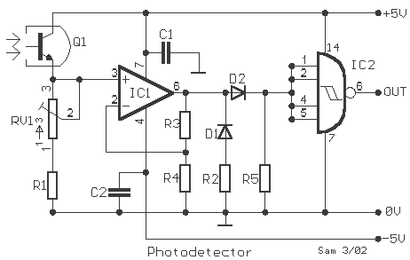
This circuit gives a low-level output when sufficient lighting is present, functioning as a light detector. It can issue a command to turn on lights when darkness falls. Its output is compatible with TTL levels, providing a low logic...
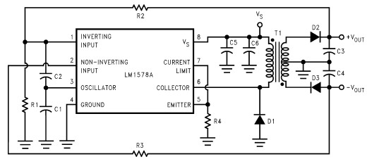
This RS232 power supply circuit diagram is a simple RS-232 line driver power supply that operates from an input voltage as low as 4.2V and delivers an output of ±12V at ±40 mA with an efficiency of better than...
Do you have disco ears? If people ask you this and you are still well below 80, you may be experiencing hearing loss, which can result from prolonged exposure to loud music. The severity of the issue may not...
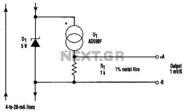
At the core of this circuit is the KTY10 temperature sensor from Siemens. This silicon sensor functions as a temperature-dependent resistor, integrated as one arm of a bridge circuit. A preset potentiometer (P1) is used to balance the bridge...
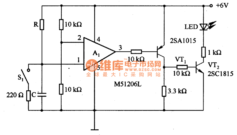
The circuit is designed to set a delay time based on the voltage Us and the resistor R. In this configuration, S1 acts as the discharge switch for capacitor C. When switch S1 is closed, the stored charge in...
The circuit diagram represents a simple yet effective intercom system entirely based on transistors. It consists of three stages along with an RC amplifier. When the pushbutton S2 is pressed, the amplifier circuit around transistor T1 is activated. The intercom...