
AM radio intermediate frequency amplification and detection circuit
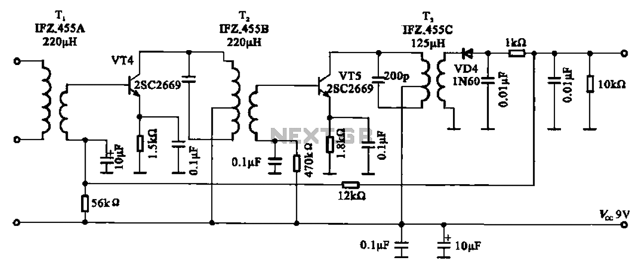
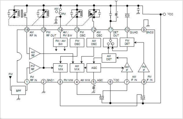
The AM radio circuit described encompasses essential components for the amplification and detection of intermediate frequency (IF) signals. The mixer serves as the initial stage, where the incoming RF signal is combined with a local oscillator signal to produce an IF signal. This IF signal is routed to the base of the transistor VT4, which is configured to amplify the signal. The collector load of VT4 connects to the primary winding of transformer T2, which is designed to resonate at 465 kHz, ensuring optimal signal transfer and amplification.
Transformer T2 plays a crucial role in filtering and isolating the desired IF frequency from unwanted signals. The inclusion of a 200 pF capacitor in parallel with the primary winding enhances the resonance, allowing for efficient signal processing. The secondary winding of T2 is connected to the base of the transistor VT5, which further amplifies the IF signal. This amplification stage is critical for maintaining signal integrity before it is sent to the detection circuit.
The output from VT5 is directed to intermediate frequency transformer T3, which serves as a coupling stage to the detection circuit. The detection circuit employs diodes VD4, which are responsible for demodulating the audio signal from the IF carrier. This process effectively removes the modulation, allowing the original audio signal to be extracted and forwarded to the audio power amplifier for further amplification and output.
Additionally, an automatic gain control (AGC) mechanism is implemented through a 12 kΩ resistor, which generates a control voltage applied to the base of VT4. This AGC signal helps maintain consistent output levels by adjusting the gain of the amplifier based on the input signal strength, thereby improving the overall performance and reliability of the AM radio circuit.AM radio shows of the IF amplifier and detector circuit. Mixer from the mixer IF output signal level of the intermediate frequency transformer after the device Ti, is applied t o the base of the intermediate frequency transistor VT4, VT4 collector load is intermediate frequency transformer primary winding T2, the primary winding 200 P parallel capacitor resonant circuit, resonant at 465 kHz, T2 secondary IF amplifier tube connected to the base of the pole VT5 by VT5 amplified IF signal, and then the intermediate frequency transformer T3 to the detection circuit, detector diodes VD4 modulated audio signal on an intermediate frequency carrier remove, transfer audio power amplifier, while forming via a resistor 12kn AGC signal is applied to the base bias on VT4.
Related Circuits
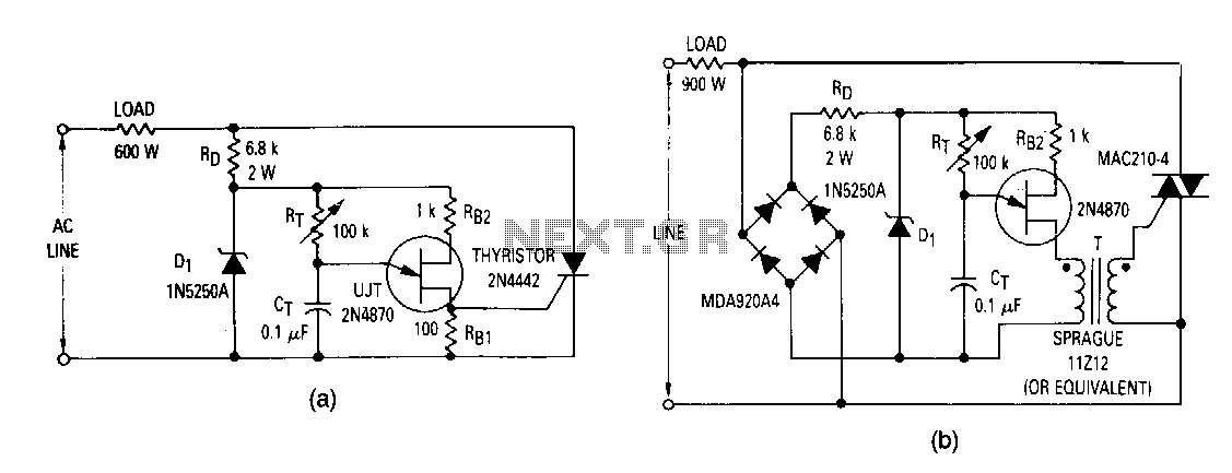
The most elementary application is a half-wave control circuit. The thyristor is acting both as a power control device and as a rectifier, providing variable power to the load during the positive half cycle and no power to the...
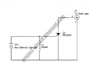
The following circuit illustrates a Slave Flash Light Control Circuit Diagram. Features include a 68mH inductor that provides an automatic trigger for the secondary flash light. The Slave Flash Light Control Circuit is designed to manage the operation of a...
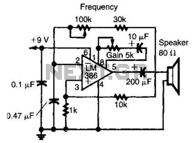
An LM386 audio power IC is configured as a feedback oscillator. It can operate with a supply voltage ranging from 6 to 12 V. The circuit is capable of driving a loudspeaker. The LM386 is a low-voltage audio power amplifier...
Telephone Tone Ringer TA31001 The UTC TA31001 is a bipolar integrated circuit designed for telephone bell replacement. It can also be used as alarms or other alerting devices. By LianShun Electronics Co., Ltd. The UTC TA31001 is a versatile bipolar...
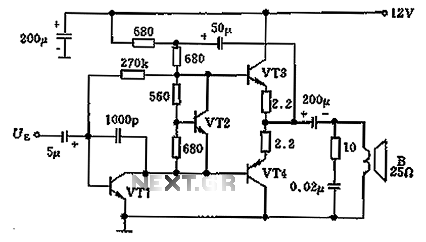
The overload protection circuit operates at a power of 650 mW with a supply voltage of 12 V and is designed for a speaker with an impedance of 25 ohms. The component specifications include: VT1 as transistor NB111EH/J, VT2...
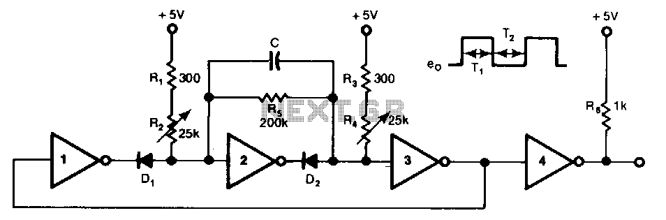
This free-running TTL square-wave oscillator features a variable frequency output spanning a 20:1 range or better. It utilizes four of the six inverters in an SN7404 chip along with additional components. The frequency of oscillation is dictated by the...
Warning: include(partials/cookie-banner.php): Failed to open stream: Permission denied in /var/www/html/nextgr/view-circuit.php on line 713
Warning: include(): Failed opening 'partials/cookie-banner.php' for inclusion (include_path='.:/usr/share/php') in /var/www/html/nextgr/view-circuit.php on line 713