
AM Radio Receiver Circuit With BF959 Transistor
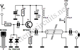
In the context of antenna systems, impedance matching is crucial for maximizing power transfer and minimizing signal reflection. The function described indicates a circuit designed to reduce the impedance of an antenna from a high value down to a standard 50 ohms. This is particularly important in radio frequency (RF) applications where mismatched impedances can lead to inefficient transmission and reception of signals.
The circuit likely employs a transformer or an LC network to achieve this impedance transformation. A transformer can be designed with specific turns ratios to step down the impedance effectively. For instance, if the high impedance is 300 ohms, a 1:3 turns ratio transformer can be used to step down to 50 ohms. Alternatively, an LC matching network consisting of inductors and capacitors can be configured in either a series or parallel arrangement to create a matching network that achieves the desired impedance transformation.
It is noteworthy that the description mentions that this impedance transformation does not involve converting a balanced signal to an unbalanced one. This suggests that the circuit is designed to maintain the signal integrity and balance, which is essential in applications where signal purity is critical, such as in RF transmission lines or balanced antenna systems.
The component selection for such a circuit would include high-frequency inductors and capacitors that can handle the specific frequency range of operation. Additionally, careful consideration must be given to the layout of the circuit to minimize parasitic capacitance and inductance, which can adversely affect performance at RF frequencies.
In conclusion, the described function emphasizes the importance of impedance matching in antenna systems, specifically focusing on stepping down high impedance to a standard value while preserving signal characteristics. This is a fundamental aspect of RF design that ensures optimal performance in communication systems.Function: step down the antenna impedance from ‘high to to 50? and not, as would be expected, to effect a change from balanced to unbalanced. Component: .. 🔗 External reference
Related Circuits
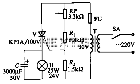
The circuit employs thyristor control. The flash frequency is determined by resistors Ri, RP, Rz, and capacitor C. By adjusting the electrical locator RP, the flash frequency can be varied from 0.5 Hz to several Hz. The described circuit utilizes...
The MAX2385 and MAX2386 LNA mixer integrated circuits (ICs) are designed for CDMA, cdma2000 1x, and GPS applications. These ICs are optimized for the Japanese frequency band of 832 MHz to 870 MHz and can also be configured for...

The phase and neutral wires from the power source have already been connected to electrical appliances such as fans and light points. According to the UPS connection diagram, an additional phase wire should be connected to those appliances where...

This circuit utilizes a 4049 integrated circuit (IC) to control a 2N2222 switching transistor. The transistor, in turn, drives a piezo transducer known as crystal 1. The circuit design begins with the 4049 IC, which is a hex inverter capable...
This integrated circuit (IC) requires fewer external components, making it simpler for beginners to assemble it on a veroboard. The original circuit was sourced from its datasheet. A slightly modified version of the circuit is presented below. This circuit...
This circuit functions as a camera switch, allowing multiple cameras to be connected to a single monitor. It can operate in both manual and automatic modes. In automatic mode, the circuit utilizes a 555 astable multivibrator to generate a...