
AM receiver
In the superhetrodyne mode, the receiver consists of a ferrite loopstick antenna, a local oscillator, mixer, an IF filter and an IF amplifier and AM detector, followed by an audio amplifier. The loop antenna is a resonant circuit made of a 760 microhenry coil wound on a 5.5 cm long ferrite rod covered with one thickness of 80 grams per square meter printer paper, in parallel with a 1000 pf capacitor. The ferrite rod was picked up at a surplus store, so I had to experiment a little to find the correct number of turns. I started by winding 100 turns closely spaced in the middle of the ferrite rod, with a tap at 50 turns. I used #30 heavy polythermaleze magnet wire. I measured the inductance between the 50 turn tap and each end of the coil, and measured it a third time for the entire 100 turns, then I calculated an inductance factor for the rod for each of the windings, and then found the average inductance factor. The inductance factor, also referred to as AL (A-sub-L) in some literature is the factor that, when multiplied by the number of turns squared, is equal to the inductance. Here, I will use the symbol K.
The experimental AM receiver is designed for operation in the Very Low Frequency (VLF) range, specifically targeting a frequency of 181.818 kHz. The design supports two operational modes: superheterodyne and direct conversion. In superheterodyne mode, the receiver architecture includes a ferrite loopstick antenna, local oscillator, mixer, intermediate frequency (IF) filter, IF amplifier, AM detector, and audio amplifier. This configuration allows for a bandwidth of 15 Hz to 3.5 kHz, enabling effective reception of AM signals within this range.
The ferrite loopstick antenna is a critical component, functioning as a resonant circuit. It consists of a 760 microhenry coil wound on a 5.5 cm long ferrite rod, which is coated with a single layer of 80 grams per square meter printer paper to enhance performance. The coil is paired with a 1000 picofarad capacitor, establishing resonance at the desired frequency. The winding process involves 100 tightly spaced turns of #30 heavy polythermaleze magnet wire, with a tap at 50 turns to facilitate inductance measurements. The inductance factor, denoted as K, is calculated based on the number of turns and is essential for tuning the antenna effectively.
In direct conversion mode, the design utilizes the SA-612 mixer and a 2N2907 transistor to manage signal processing. The mode switch determines the operational state of the receiver by controlling the power supply to the MK-484 detector and the shunting of the direct conversion signal. This flexibility allows for experimentation and verification of various component interactions, contributing to a comprehensive understanding of VLF reception techniques.
Powering the entire circuit is achieved via a +5 volt regulator, with the option to utilize a 9-volt battery or any suitable power source providing +8V or higher. This design consideration ensures that the receiver remains operational under various power supply conditions, facilitating field testing and experimentation. The combination of these elements results in a versatile AM receiver capable of meeting the needs of VLF signal reception and experimentation.This is a description of an experimental AM receiver for VLF. It is crystal controlled to receive 181.818 kHz (more or less) and operates as either a single conversion superhetrodyne or a direct conversion receiver. The bandwidths are expected to be 15 Hz to 3.5 kHz in superhet mode and 15 Hz to 10 kHz in the direct conversion mode.
Operation is from a single +5 volt regulator and it can be powered from a 9 volt radio battery or other source of +8V or higher. The reason I built this was to verify some of my assumptions about these components would work together, having had numerous discussions of the SA-612/MK-484 and SA-612 direct conversion receiver concepts over the last year or so with my friend Jeff, besides that, I want to have a direct conversion receiver on hand for some planned experiments.
Depending up the state of the mode switch on the left, either pin 8 or pin 9 of the AT90S2313 goes high. When pin 8 goes high, it supplies power to the MK-484 (ZN-414 replacement - an integrated IF/AM detector).
When pin 9 goes high, it stops the 2N2907 from shunting the direct conversion signal at the output of the SA6-12. In the superhetrodyne mode, the receiver consists of a ferrite loopstick antenna, a local oscillator, mixer an IF filter and an IF amplifier and AM detector, followed by an audio amplifier.
The loop antenna is a resonant circuit made of a 760 microhenry coil wound on a 5.5 cm long ferrite rod covered with one thickness of 80 grams per square meter printer paper, in parallel with a 1000 pf capacitor.. The ferrite rod was picked up at a surplus store, so I had to experiment a little to find the correct number of turns.
I started by winding 100 turn closely spaced in the middle of the ferrite rod, with a tap at 50 turns. I used #30 heavy polythermaleze magnet wire. I measured the inductance between the 50 turn tap and each end of the coil, and measured it a third time for the entire 100 turns, then I calculated an inductance factor for the rod for each of the windings, and then found the average inductance factor.
The inductance factor, also referred to as AL (A-sub-L) in some literature is the factor that, when multiplied by the number of turns squared, is equal to the inductance. Here, I will use the symbol K. 🔗 External reference
Related Circuits
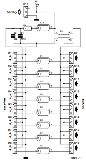
Receiver interference is a common issue among model builders. Preventive measures, such as ferrite beads fitted to servo cables, are frequently employed in larger models and electrically driven models to prevent the cables from acting as antennas and radiating...
The FM radio receiver with PLL designed by A. Zaharov continues to attract the interest of radio amateurs. According to a publication in the magazine "Radio," one of the primary drawbacks of this type of detector is its low...
This article discusses the functionality of a super-regenerative FM receiver. The principle behind this receiver utilizes high-gain miniature integrated circuits, resulting in a simple and innovative circuit design. It achieves the performance level of standard FM receivers while addressing...
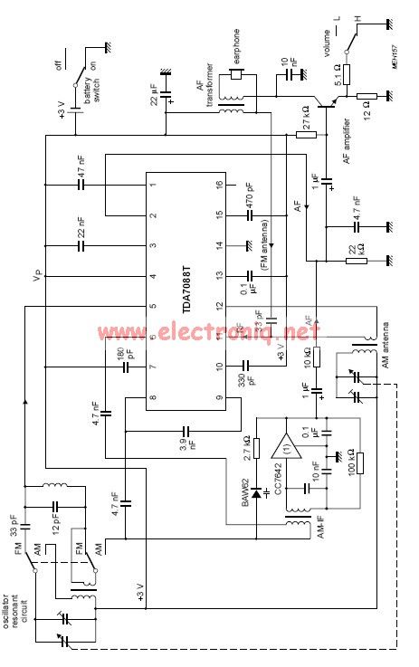
The TDA7088 incorporates a frequency-locked loop (FLL) system with an intermediate frequency (IF) of approximately 70 kHz. This circuit can be powered using a 3-volt battery cell or a regulated power supply. The TDA7088 is designed for use in various...
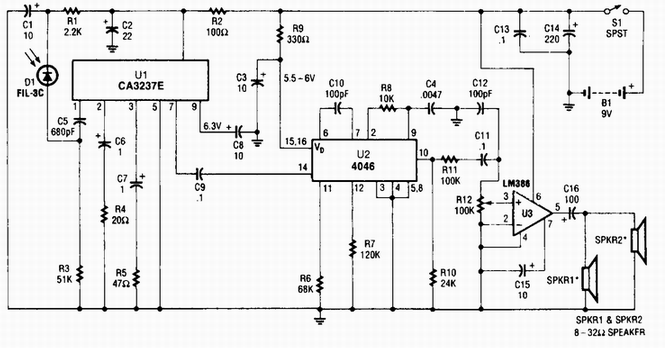
A photodiode D1 feeds a high-gain infrared (IR) remote control preamplifier IC, specifically a CA3237E. U2 is a phase-locked loop (PLL) frequency modulation (FM) detector tuned to approximately 100 kHz. The output from the detector is amplified by U3,...
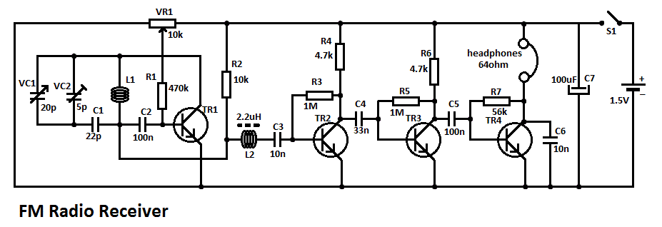
This simple FM radio receiver circuit consists of a regenerative RF stage, TR1, followed by a two or three-stage audio amplifier comprising TR2 to TR4. In some areas... This circuit is designed to receive FM radio signals, utilizing a regenerative...