
wireless ir headphone receiver
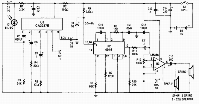
The circuit begins with the photodiode D1, which serves as the light-sensitive element that detects infrared signals emitted by a remote control. When IR light strikes the photodiode, it generates a small photocurrent proportional to the intensity of the incoming light. This current is then fed into the high-gain preamplifier IC, CA3237E, which amplifies the weak signal from the photodiode to a more usable level.
Subsequently, the amplified signal is sent to the PLL FM detector, designated as U2. This component is tuned to a frequency of around 100 kHz, allowing it to demodulate the frequency-modulated signal received from the preamplifier. The phase-locked loop configuration ensures that the output remains synchronized with the incoming signal, providing a stable and reliable detection of the transmitted data.
The output from the PLL detector is then processed by U3, which serves as an additional amplification stage. This stage is critical for driving audio output devices such as speakers or headphones. The amplification ensures that the audio signal is sufficiently strong to be heard clearly when played through these devices.
Overall, this circuit design effectively combines photodetection, signal amplification, and audio output, making it suitable for applications in IR remote control systems. The careful selection of components and their configuration allows for efficient signal processing and reliable performance in various electronic devices.A photodiode Dl feeds high gain IR remote control preamp 1C, a CA3237E. U2 is a PLL FM detector tuned to around 100 kHz. The detector output is amplified by U3 and it can drive a speaker or a set of headphones. 🔗 External reference
Related Circuits
I built this headphone amplifier for dynamic headphones based on my rules of proper audio design. People who know my designs will realize that this amplifier is much more than just a headphone amp. It is a pure class...
This AM radio receiver circuit utilizes the TDA1083 radio IC, which is suitable for constructing a simple medium frequency (MF) band radio. The schematic operates within a frequency range of 300 kHz to 3 MHz. The circuit is straightforward...
The MC13136 circuit is not easy to find so I have replaced it with a new receiver circuit called SA615. This is a basic FM receiver with very good performance and sensitivity. In my super receiver I used a...
Even if the circuit is simple, it complies with all conditions regarding distortion and frequency response. The input resistance is 250K ohms, and it can drive loads ranging from 100 ohms to 2K ohms. The described circuit is a fundamental...
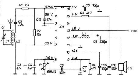
The transmitter provides an optical link (infrared) for headphones. Three infrared LEDs (IR) are powered by T1, with P1 used to adjust the current level. The current consumption of this headphones infrared transmitter is approximately 60mA at 9V. The infrared...
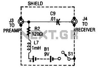
The purpose of the receiver/interface circuit is to pass RF to the receiver through capacitor C9, while adding DC power to the feedline through resistor R2 and RF choke L7. The receiver/interface circuit is designed to facilitate the transmission of...
Warning: include(partials/cookie-banner.php): Failed to open stream: Permission denied in /var/www/html/nextgr/view-circuit.php on line 713
Warning: include(): Failed opening 'partials/cookie-banner.php' for inclusion (include_path='.:/usr/share/php') in /var/www/html/nextgr/view-circuit.php on line 713