
Stepper Motor ControllerCircuit Based On The 7404 IC
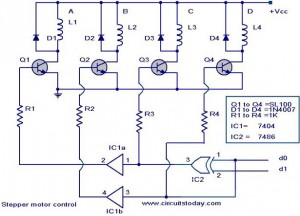
The stepper motor controller circuit utilizing the 7404 IC is designed to drive a stepper motor with a straightforward and efficient approach. The 7404 IC, a hex inverter, plays a crucial role in generating the necessary control signals for the stepper motor operation.
In this configuration, the circuit typically includes the following components: the 7404 IC, a power supply, the stepper motor, and additional passive components such as resistors and capacitors for signal conditioning. The power supply provides the required voltage and current to both the 7404 IC and the stepper motor, ensuring reliable operation.
The stepper motor is controlled by sending a sequence of pulses to its windings, which are managed by the output of the 7404 IC. The inverters in the IC convert the input control signals into the appropriate logic levels needed to energize the motor phases in the correct order, allowing for precise control of the motor's position and speed.
Additionally, the circuit can be enhanced with features such as speed control through pulse width modulation (PWM) or the inclusion of a microcontroller for more complex control schemes. Implementing such features can significantly improve the performance and versatility of the stepper motor controller, making it suitable for various applications in robotics, automation, and precision positioning systems.
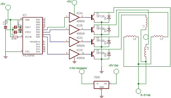
Overall, this stepper motor controller circuit exemplifies a basic yet effective method of controlling stepper motors using the 7404 IC, showcasing simplicity and functionality in electronic design.The following circuit shows about Stepper Motor Controller Circuit Diagram. This circuit based on the 7404 IC. Features: simple stepper motor . 🔗 External reference
Related Circuits
This simple and inexpensive yet powerful square wave oscillator can provide oscillation for any MOSFET-based inverter or UPS. The circuit features a central integrated circuit (IC), specifically the CD4047, with the HCF4047BE model from ST Microelectronics utilized. This design...
The 555 IC is wired as an astable and the frequency is constant and independent of the duty cycle, as the total resistance (R charge + R discharge, notice the diode) is constant and equal to 22Kohm (giving a...
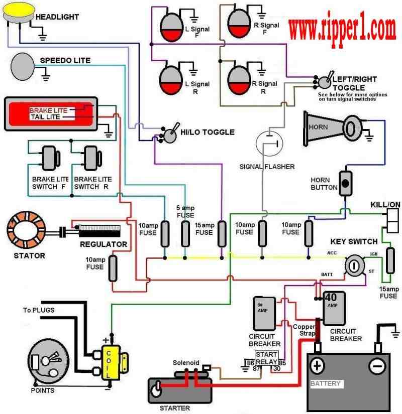
Customs by Ripper - A technical page focused on basic wiring for any vehicle, particularly motorcycles. The page serves as a valuable resource for individuals seeking to understand the fundamentals of vehicle wiring, with a specific emphasis on motorcycles....
Since completing the degree in April, there has been a pursuit for employment. The search has been gradual, but there is optimism for future financial success. In the context of electronic schematics, the pursuit of employment can be likened to...
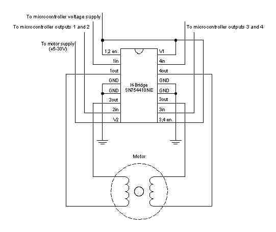
A stepper motor is a motor controlled by a series of electromagnetic coils. The center shaft has a series of magnets mounted on it, and the coils surrounding the shaft are alternately energized or de-energized, creating magnetic fields that...
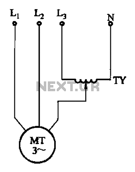
The circuit illustrated in Figure 3-175 features a regulator connected between one phase and neutral. It is designed for use with a 380V torque motor. This method offers advantages over the serious line imbalance approach, resulting in improved operating...