
am/fm radio & Pilot 100 stereo demodulator
The described circuit enhancements are a response to the evolving demands of FM broadcast reception, particularly in environments with multiple active stations and varying power levels. The integration of the pentagrid converter, specifically the 6BE6 tube, showcases advancements in mixer technology, allowing for improved isolation between the local oscillator and the input signal, thereby enhancing overall receiver performance. The use of antiparallel diodes for peak clipping is a practical approach to mitigate distortion caused by signal peaks exceeding the operational limits of the receiver circuitry.
The implementation of a blend control potentiometer serves to optimize audio output by adjusting the phase relationship between stereo channels, which can effectively reduce noise artifacts that may arise from stereo broadcasts. The dual diode networks employed in the 19 kHz limiter provide flexibility in signal processing, allowing for adjustments based on the specific characteristics of the received signal.
The dynamic limiter's role in the Espey 200 receiver exemplifies the need for adaptive circuitry that can accommodate varying signal conditions without compromising audio fidelity. The careful selection of components, such as the polypropylene capacitor for DC blocking, reflects a thorough understanding of the interactions between different stages of the receiver circuit. Overall, these modifications represent a comprehensive approach to enhancing receiver performance in challenging broadcast environments, ensuring clearer audio output and improved reception of weak signals.As the number of stations increased and the power levels also increased; receiver performance had to improve. The pentagrid converter, such as the 6BE6 tube (British EK90 valve), was introduced which was optimized for mixer performance.
This included the isolation of local oscillator and input signal as well as allowing the first grid and cathode to work in an oscillator configuration. These tubes allowed a closer approximation to the multiplication of the two sine waves which produced fewer spurious mixing products. The British used a 7 grid tube with similar multiplication properties in FM broadcast receiver demodulators.
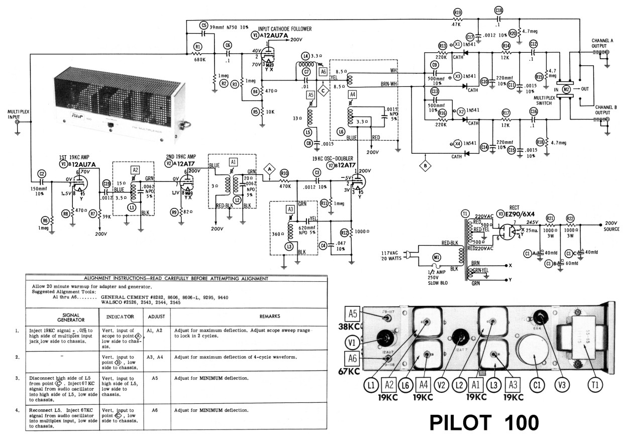
They picked signals off the primary and secondary of the last IF double tuned transformer (which were 90 degrees out of phase) and multiplied them. The simplest modification seemed to be to use antiparallel diodes across the signal path to clip positive and negative peaks outside the +/- 0.
6 volt range (for two silicon diodes). I put the limiter at point A in the schematic. The limiter includes a 10k resistor between tank circuit A1 and the 470k resistor with the antiparallel diodes connected between ground and the connection point between the 10k and 470k resistors. I put a switch in the circuit to switch the diodes in and out of the circuit to compare the effect with and without the limiter.
WMUC (88. 1 MHz) broadcasts with 10 watts of power and when the Pilot 100 is set to stereo, usually a grumbling splatter sound can be heard during silent passages which seems to be from interference from nearby stations, like NPR on 88. 5 MHz and probably other stations. Sometimes when WMUC is off the air I can hear a lot of noise at 88. 1 MHz which sounds like other stations bleeding over into that frequency, as well as another distant station on 88.
1 MHz. Switching the diodes into the circuit essentially causes the grumbling splatter sound to disappear, but some noise ccan still be heard at a lower level during silent passages. Its a distinct improvement. Before this, I put a 500k pot having a switch in the Pilot 100 between the slide switch stereo outputs as a blend control which can be switched on and off and adjusted between stereo and mono.
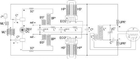
Blending the left and right outputs tends to reduce noise since the stereo noise is out of phase in both channels. I added a second diode network to the 19 kHz limiter which clips at a higher voltage. An On-Off-On switch was also added to switch either diode network in or out of the circuit. The switch is positioned to get the most stable operation and best signal to noise ratio. I tried adding another limiter, this time in the Espey 200 receiver. I tried putting a modified anti-parallel diode dynamic limiter based on limiter 55 in figure 1 in US patent 3080453, at the control grid of the 6AU6 2nd FM IF amp.
I put a 2. 5 mf 220 VAC polypropylene capacitor between the grid of the 6AU6 in the Espey and the dynamic limiter to block DC and prevent it from affecting the bias on the control grid of the 6AU6. I also put a switch between the dynamic limiter and ground so I can switch it in and out of the circuit.
The dynamic limiter tends to affect the tuning of the IF transformer a little bit which I had to tune after putting it in the radio. It makes a big difference with weak stations, less noise and better stereo image. Both the dynamic limiter in the Espey and the 19kHz limiter in the Pilot 100 are needed with weak stations to get the best results.
Espey 200 with dynamic limiter shown below (two big white 2. 5 mf polypropylene capacitors, two green. 047 polystyrene capacitors and two hard to see silicon diodes and 8. 2k resistors connected to a switch in the back of the Espey 200) 🔗 External reference
Related Circuits
In the measurement of the changed supply current, the return line of the power side is grounded. Sometimes, it cannot be connected to the shunt resistor between the casing and the rack. The INA168 is a current detecting circuit...
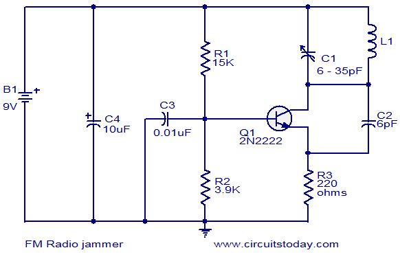
This circuit can be utilized to jam FM radios in its vicinity. It is a classic single transistor oscillator operating in the VHF region. The working principle of the circuit is straightforward. Powerful VHF oscillations generated by the circuit...
This is a schematic diagram of a stereo audio amplifier for a car. The circuit is powered by a single IC, the TDA1553, along with some external components. This IC is designed to manage the stereo car audio system....
The following circuit illustrates a Radio Remote Control Circuit Diagram. This circuit is based on the UM91214B IC. Features include the use of DTMF (dual-tone multi-frequency) technology. The Radio Remote Control Circuit utilizes the UM91214B integrated circuit, which is specifically...
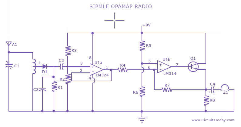
A low-cost, simple radio circuit schematic using an operational amplifier. This radio circuit diagram consists of a sensitive audio amplifier that receives strong signals. The presented radio circuit schematic utilizes an operational amplifier (op-amp) to create a cost-effective and straightforward...
This circuit is of a 2x 2,500W RMS stereo amplifier, super-light and without switching-mode power supply. The circuit just shows a channel, and the power supply that it assists to the two channels. The audio circuit should be duplicated,...
Warning: include(partials/cookie-banner.php): Failed to open stream: Permission denied in /var/www/html/nextgr/view-circuit.php on line 713
Warning: include(): Failed opening 'partials/cookie-banner.php' for inclusion (include_path='.:/usr/share/php') in /var/www/html/nextgr/view-circuit.php on line 713