
Enhance Synchronous-Rectification Control In Flyback Converters

Concerning losses, for a diode, the forward-conduction power loss is the product of the forward voltage and current. For a MOSFET, it is calculated as I²RDS(ON). For instance, with a diode exhibiting a standard 0.6 V forward voltage and a 4 A current, 2.4 W is dissipated as heat. Conversely, if a MOSFET has an RDS(ON) of 10 mΩ, the loss at 4 A is merely 0.16 W. This indicates that at 4 A, the MOSFET dissipates 93% less power, leading to a lower junction and case temperature, which may allow for a smaller heat sink or none at all. Theoretically, power-loss parity between the diode and MOSFET occurs at a current level of 60 A. However, in practical scenarios, before achieving power-loss parity in a real circuit, a MOSFET with a lower RDS(ON) would typically be selected, or devices may be paralleled, or a different architecture may be chosen. Although synchronous rectification offers substantial efficiency and thermal management benefits over diode rectification, these advantages come at a cost: a gate-control signal is required to operate the FET properly. A common method for gate control involves a current transformer, a comparator, and a gate-driver stage. A simplified schematic of this arrangement illustrates that the current transformer senses the secondary current, producing a scaled copy on its load impedance, yielding a voltage proportional to the current while retaining polarity information. The comparator detects this voltage and activates the MOSFET through the driver when the secondary current flows in the forward direction. Despite its conceptual simplicity, the current-transformer-based SR control presents several challenges. The first challenge arises from the nature of transformers, whether voltage or current types, as they are AC-coupled devices. Consequently, the secondary signal from the current transformer is bipolar, necessitating downstream signal processing that accounts for this characteristic. This complicates the power-transformer design, requiring an additional secondary-winding segment and the incorporation of a rectifier and filter to establish a second rail for the comparator and driver. The second challenge is that the complete circuit may require as many as 15 components, which, along with their routing, demand a significant amount of PCB area comparable to that of a feedback control circuit. A third challenge pertains to timing considerations.
In summary, the transition from diodes to synchronous-rectification MOSFETs in flyback converters offers significant advantages in efficiency and thermal management, albeit with increased complexity and the need for sophisticated control circuits. The evolution of these technologies reflects ongoing efforts to enhance performance in power conversion applications.The transition from diodes to synchronous-rectification (SR) MOSFETs in secondary circuits of flyback converters increases with each new generation of MOSFETs, improving performance at little or no cost penalty. SR MOSFETs can be more efficient than diodes, allowing lower operating temperatures and smaller heat sinks, or no heat sinks at all.
Howe ver, they require a control circuit to manage their switching behavior in order to emulate a diode. The usual synchronous rectifier control method in today`s commercial power supplies involves deriving the logic signal for the controller from the secondary of a current transformer. There is a better way, though. Traditionally, flyback converters were well suited for applications requiring power levels less than 150 W.
Their major appeal was simplicity and low cost. Beyond 150 W, and certainly at power levels of 200 W and beyond, the half-bridge- and forward-converter were the standard topologies. The major problem with flybacks, whether they were implemented with diodes or SR MOSFETs, was semiconductor conduction losses.
As with all isolating power-converter topologies, flybacks employ a transformer on the secondary, on which resides a rectifier. The simplest configuration uses a half-wave rectifier diode on either the high or low side ( Fig. 1a ). Synchronous rectification combines a MOSFET with some kind of control for turning the device on or off so that it emulates the diode commutation of the ac from the transformer.
The synchronous approach provides greater efficiency, albeit with a corresponding tradeoff in complexity and cost ( Fig. 1b ). What kind of losses are we talking about For a diode, the forward-conduction power loss is simply the product of the forward voltage and current.
For a MOSFET, it`s I2 RDS(ON). When a diode has a standard 0. 6-V VF, a 4-A current turns 2. 4 W into heat. And, if a MOSFET`s RDS(ON) = 10 m ©, the loss at 4 A is 0. 16 W ( see the table ). At 4 A, the MOSFET dissipates 93% less power, leading to a lower junction and case temperature, meaning that it requires either a smaller heat sink or no heat sink at all. Theoretically, for the diode and MOSFET characteristics in the example, power-loss parity doesn`t occur until current reaches 60 A.
In practice, long before you reach power-loss parity in a real circuit, you would choose a MOSFET with a lower RDS(ON), parallel a pair of devices, or choose a different architecture. Though SR brings significant efficiency and thermal-management advantages over diode rectification, those advantages don`t come for free: You need a gate-control signal to properly operate the FET.
A popular approach to gate control uses a current transformer, a comparator, and a gate-driver stage. A simplified schematic of this arrangement appears in Figure 2a. The current transformer senses the secondary current, imposing scaled copy on its load impedance, which results in a voltage proportional to the current, preserving the polarity information.
The comparator detects this voltage and turns on the MOSFET through the driver when the secondary current conducts in the forward direction. Though conceptually simple, the current-transformer-based SR control presents a few challenges. The first derives from the fact that transformers, be they voltage or current transformers, are ac-coupled devices.
The current transformer`s secondary signal, therefore, is bipolar, so the downstream signal processing must take that into consideration. This complicates the power-transformer design by an additional secondary-winding segment and adds a rectifier and filter to strike a second rail for the comparator and driver.
The second challenge is that in its full implementation, this circuit requires as many as 15 components. These components, and their associated routing, require a large pc-board area comparable to that of a feedback control circuit.
A third challenge relates to timing. As 🔗 External reference
Related Circuits
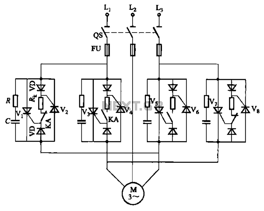
The circuit depicted in Figure 3-69 is designed for applications requiring frequent timing control for motor reversing operations. In this configuration, thyristors V1, V2, V7, and V5 are utilized for positive control of rotation, while thyristors V3, V4, and...
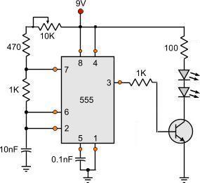
This is a simple circuit that anyone can create for enjoyment. The project originated when there was an attempt to control a TV using the serial port of a computer. It took only a few minutes to grasp the...
This Project is used to indicate the temperature and it is also used as controller. The system will get the temperature from the IC and it will display the temperature over the seven segment display and this temperature was...
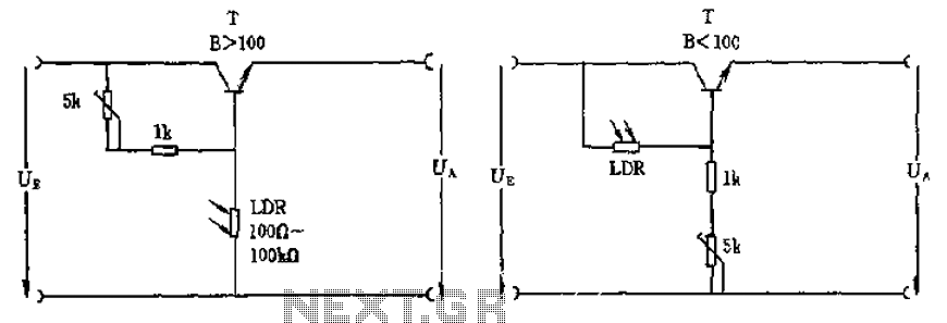
The circuit depicted involves a photoresistor (LDR) connected to a transistor, which operates at either a high or low level based on light conditions. The amplification factor of the transistor is 100, which is adequate for the application. The...
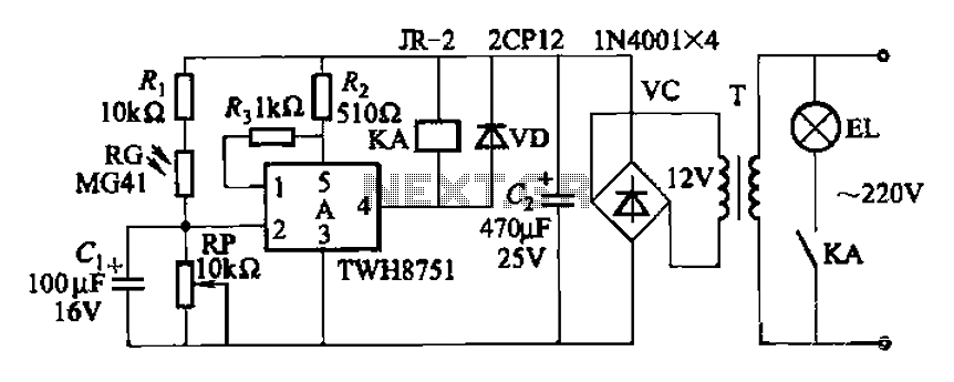
The adjustment potentiometer RP can modify the sensitivity of the device. Capacitors C1 function as an anti-light interference mechanism for instantaneous action. The adjustment potentiometer (RP) is a variable resistor that allows for fine-tuning of the device's sensitivity. By altering...
The circuit is compatible with all 2323 chips, but it is optimized for the AT90LS2323, which operates at a voltage range of 2.7 to 6 volts. The microcontroller utilized in this design is the AT90S2323, which functions effectively within...