
am transmitter circuits
The AM transmitter circuit is designed for simplicity and effectiveness in transmitting audio signals over short distances. The core of the circuit is the RF oscillator, which utilizes Q1 to generate the carrier frequency. The regenerative feedback loop established by connecting the base and collector enhances the amplitude of oscillations, allowing for stable signal generation. The tank circuit, composed of L1 and VC1, defines the frequency of oscillation, which is adjustable to accommodate different transmission needs.
Capacitor C7 serves as a coupling element that ensures the oscillation signal is effectively transferred through the inductor L1, while C2's role in coupling the collector and emitter allows for efficient signal modulation. The careful selection of R2 is essential; it not only stabilizes the oscillation but also sets the input impedance to a level that minimizes distortion from the modulating audio signal.
Q2 amplifies the modulated signal, ensuring that the output is strong enough for transmission. The decoupling capacitor C5 is critical in maintaining signal integrity by isolating the power supply variations from the amplifier's performance. The use of an electric condenser microphone as the audio input provides high fidelity, making the circuit suitable for various audio applications.
The addition of a wire antenna can significantly enhance the transmission range, making this AM transmitter circuit a practical solution for short-range audio broadcasting applications. Overall, this circuit exemplifies a straightforward approach to AM transmission, utilizing readily available components and clear design principles.The AM Transmitter circuits in two and a half, audio amplifier and an RF oscillator. The oscillator is built around Q1 and associated components. Tank circuit L1 and VC1 is melodious from about 500kHz to 1600KHz. These components can be used from an old MW radio, if available. Needs Q1 regenerative feedback to oscillate and this is achieved by con necting the base and collector of Q1 to the opposite end of the tank circuit. 1nF capacitor C7, the signal pair from the bottom to the top of L1, and C2, 100pF ensures that the oscillation is passed from collector to emitter, and through the internal base emitter resistance of transistors, back to base again. R2 has an important role in this series. Ensure that the oscillations will not be pushed to the ground through the emitter is very low internal resistance, returning from Q1, and also increases the input impedance so that the modulating signal will not be encouraged.
Oscillation frequency is adjusted with VC1. The following is a schematic drawing: Q2 is the cable as a common emitter amplifier, C5 decoupling the emitter resistor and realize the full benefits of this phase. Electric condenser microphone is mic and the amount of AM modulation is adjusted with the 4. 7k preset resistor P1. The antenna is not needed, but 30cm of wire can be used on the collector to increase transmitter range.
🔗 External reference
Related Circuits
A pair of BC548 transistors has been utilized in this circuit. Although they are not specifically designed for RF applications, they still provide satisfactory performance. An ECM microphone from Maplin Electronics, model FS43W, has been employed. This is a...

This 3V FM transmitter circuit is one of the simplest and most effective basic transmitters, offering a commendable transmitting range. It is remarkably powerful considering its small component count and 3V operating voltage. It can easily cover over three...
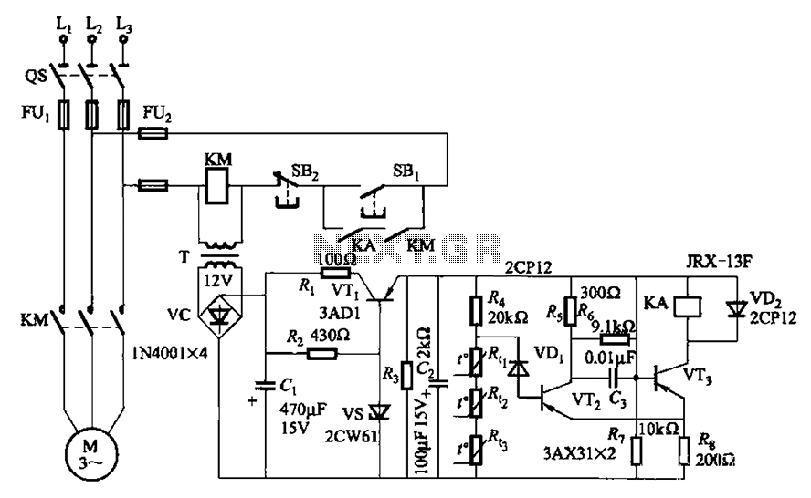
A P-type transistor (VT2, VT3) and other components form a common emitter-coupled trigger, functioning as a Schmitt trigger device. This setup serves as a switching circuit to detect changes in the resistance of a PTC thermistor, thereby controlling the...

A voltage comparator is a device that compares the voltages at its two inputs and generates an output based on the comparison. It produces a high output when the positive input exceeds the negative input and a low output...

A basic circuit of the transistor UHF radio transmitter with a surface acoustic wave resonator (SAW) is presented. The SAW is utilized as a positive feedback element connected between the transistor's base and an LC network in parallel. In...
This circuit transmits a continuous audio tone on the FM broadcast band (88-108 MHz), which can be utilized for remote control or security applications. The circuit draws approximately 30 mA from a 6-9 volt battery and has a reception...
Warning: include(partials/cookie-banner.php): Failed to open stream: Permission denied in /var/www/html/nextgr/view-circuit.php on line 713
Warning: include(): Failed opening 'partials/cookie-banner.php' for inclusion (include_path='.:/usr/share/php') in /var/www/html/nextgr/view-circuit.php on line 713