
Wireless Transmitter

The circuit design is characterized by its simplicity and effectiveness in transmitting audio signals over short distances. The use of a surface acoustic wave resonator enhances the stability and performance of the transmitter by providing a reliable feedback mechanism, which is crucial for maintaining oscillation in the RF stage. The oscillator stage (Q1) plays a pivotal role in generating the RF carrier signal, while the modulator stage (Q2) effectively combines the audio input with the RF signal, allowing for amplitude modulation.
The components involved in the circuit are selected for their specific roles. Resistors R1, R2, and R3 are used to bias the transistor Q1, ensuring it operates in the correct region for oscillation. The tank circuit, formed by L1, C3, and C4, is critical for determining the oscillation frequency and ensuring that the feedback is appropriately phased to sustain oscillation. The modulation stage, utilizing Q2, is designed to handle the incoming audio signal, with the bypass capacitor C6 ensuring that RF noise does not interfere with the audio signal path.
The circuit can be powered by a standard 9V battery or an external power supply, providing flexibility in its deployment. The range of the transmitter is determined by the antenna design and the modulation depth, with the potential to reach several hundred meters in open air. The tuning mechanism, which involves adjusting the variable capacitor and coils, allows for fine-tuning of the operating frequency within the AM band, accommodating various audio sources.
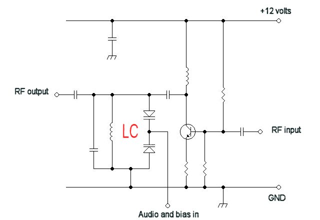
In summary, this basic UHF radio transmitter circuit demonstrates fundamental principles of RF transmission, modulation techniques, and component interaction, making it an excellent educational tool for understanding AM transmission technology.A basic circuit of the transistor UHF radio transmitter with surface acoustic wave resonator (SAW), and the SAW is used as a positive feedback element connected between the transistor VT base and LC network in parallel. Figure (b) shows another basic transistor UHF radio transmitter circuit with the surface acoustic wave resonator
, in this circuit, SAW is connected between the transistor`s base and emitter; the phase relationship between them is 180 degree. (View) This transmitter is basic but allows transmission of audio to an AM radio. It consists of an RF oscillator operating in the AM broadcast band, together with a modulator stage, which mixes the incoming audio and the RF.
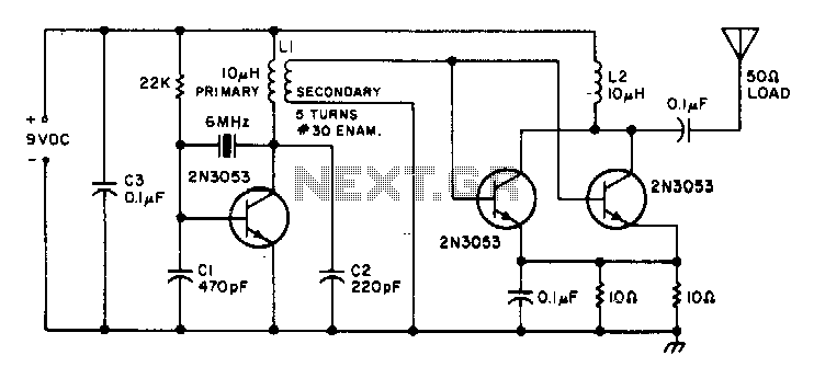
A signal appears on the output, which has an AM component that can be picked up on a nearby AM radio receiver. The transmitter consists of oscillator stage Q1 and modulator/buffer stage Q2. Q1 is biased via R1, R2, and R3. L1, C3, and C4 form the tank circuit with feedback network C3-C4 providing feedback to the emitter of Q1.
RF voltage at the junction of C3 and L1 drives buffer/modulator stage Q2. Q2 is biased by base current produced by RF rectification in the base emitter junction of Q2. C6 is an RF and AF bypass capacitor. C9, C10, and L2 form the tank circuit for the collector of Q2. RF is taken from the junction of C9 and C10 and fed to a short-wire antenna. Audio is fed to modulator Q2 via C8 and isolation resistor R5 and mixes with the RF signal in the collector circuit of Q2, producing a signal that has sum and difference frequencies if the RF carrier and AF input along with the carrier signal. An AM signal appears at the collector of Q2. Audio with an RMS voltage equal to about 0. 7 times the collector voltage of Q2 is needed for full modulation of the output. Because of the high level of audio needed, the modulation obtained from this circuit is somewhat limited with conventional audio sources because several volts of audio into a few hundred ohms is needed.
The circuit demonstrates the principle of an AM transmitter, however, and with a suitable audio drive level, produces a well modulated AM signal. 5 Responses to Basic low power AM transmitter (View) This is a nice 2 Watts FM transmitter. It has a Super-Sensitive pre-amplification with BC109 and BC177 with more than 100% signal modulation.
The job finish the 2N2219 by Motorola. For the Coils you should use 1mm wire(enameled), L1= 3 turns - 10mm diameter, L2= 1 turn - 10mm diameter. R9 trimmer controls the modulation gain. The tunning is easy by controlling C9 trimmer (88-108 MHz). The RFC J should be the VK220J with ferrite (VK200 is not suitable). Source: NEXT. GR (View) The Circuit shown can transmit voice to exceptionally good range. Tune trimmer to hear the signal to your near radio. Frequency range is 88-108 MHz. Max current consumption is 30mA. You can power the bug with a 9Volt Battery, or you can plug a power supply to feed in 9-12 Volts. Source: NEXT. GR (View) This 1 channel infrared transmitter/receiver remote control is the cheapest and simplest you can find.
The transmitter transmits a sequence of pulses on 36 KHz frequency carrier. The diodes are Schottky type because of their low voltage drop (only 0. 2V). The ripple counter 74HC4060 contains an oscillator which controls the frequency carrier to be 36KHz. Source: NEXT. GR (View) This Transmitter can be powered by a battery 9V (not more than 12V). You can connect your music source where the microphone is or use a simple condenser microphone. The range of signal can reach 400 meters in open air. The wide range of frequency is up to you. Tune it at FM band (88-108) or TV band 40-80Mhz. Play with the Coil and the variable capacitor to tune it to any frequency you want as long as you got the receiver. (View) IT usesDTMF encoder output dual tone multi-frequency coded signal to modulate the transmitted carrier frequency.
It can form a DTMF encoded 🔗 External reference
Related Circuits
This circuit was formed to create a wireless alarm from a normal magnetic contact. By fixing the magnet to the leaf of a door, or swing of a drawer, it is easy to reveal the opening. To transmit the...
An FM transmitter circuit that utilizes a low power configuration, employing an operational amplifier as an audio preamplifier and a single transistor to function as the RF amplifier. This FM transmitter circuit is designed for low power applications, making...

This circuit explains alternate wireless switching using an ultrasonic sensor. The distance of the switching range should be more than 10 meters. The described circuit employs an ultrasonic sensor to facilitate wireless switching, allowing for the activation or deactivation of...
This circuit is sourced from a remote control tarantula transmitter that operates at a frequency of 49.86 MHz. The schematic is also available on the FCC website by searching for the FCC ID. This device complies with Part 15.235...
For a fixed frequency transmitter, a common method is to use a resonant quartz crystal in a crystal oscillator to establish the frequency. In transmitters where the frequency must be variable, several options are available. It is often the...
This is a small transmitter designed to fit inside a plastic Easter egg. It delivers approximately 1 W of measured RF output into a 50-ohm dummy load and does not generate any heating issues within the circuit. The crystal...