
AMP Hexadecimal Rotary Switch
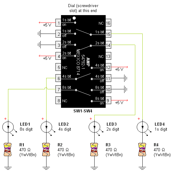
The AMP hexadecimal switch is a 16-position rotary switch designed for applications requiring multiple selectable options. This switch features a screw slot actuator that allows for manual rotation and selection of positions. Each position of the switch corresponds to a unique electrical connection, enabling the user to route signals or power to various outputs based on the selected setting.
The schematic representation of the switch typically includes pinouts that illustrate the electrical connections associated with each position. The pin configuration is essential for integrating the switch into a larger circuit, ensuring proper functionality and signal routing. The switch's design allows for ease of installation and maintenance, with the screw slot actuator facilitating user interaction.
In applications, this type of switch is commonly employed in control panels, instrumentation, and various electronic devices where multiple operational modes are required. The robust construction of the AMP switch ensures reliability and longevity, making it suitable for both consumer and industrial applications.
When designing a circuit that incorporates the AMP hexadecimal switch, it is crucial to consider the electrical ratings, such as voltage and current limits, to prevent damage and ensure optimal performance. Additionally, the layout of the surrounding components should accommodate the physical dimensions of the switch, allowing for effective integration into the overall system design. Proper labeling and documentation of the switch's positions in the schematic will aid in troubleshooting and user operation, enhancing the overall usability of the electronic device.Pictures and a sample schematic (including pinouts) of an AMP hexadecimal (16-position) switch with screw slot actuator.. 🔗 External reference
Related Circuits
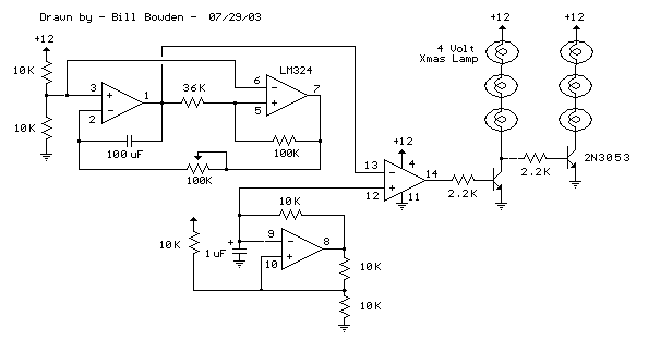
This circuit resembles the "Fading Red Eyes" circuit found in the LED section, designed to fade a pair of red LEDs. In this iteration, the lamps are dimmed by adjusting the duty cycle, allowing for the use of higher...
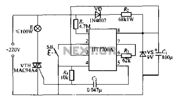
The HT7700A ASIC is designed for stepless dimming of lights, utilizing a single button control mechanism. It offers 96 levels of brightness adjustment. The HT7700A is fabricated using a CMOS process and comes in a standard D1P-S-pin package. The...
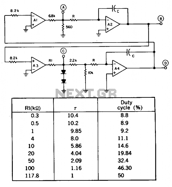
A quad op amp can simultaneously generate four synchronized waveforms. The two comparators (A1 and A3) produce square and pulse waves, while the two integrators (A2 and A4) generate triangular and sawtooth waves. Resistor R1 sets the duty cycle...
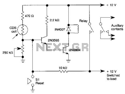
When light strikes the CDS cell, it activates the transistors, which in turn energizes the relay, causing it to latch. Pressing switch SI grounds the base of the 2N3565 transistor, thereby resetting the relay. Additionally, a 250 k potentiometer...
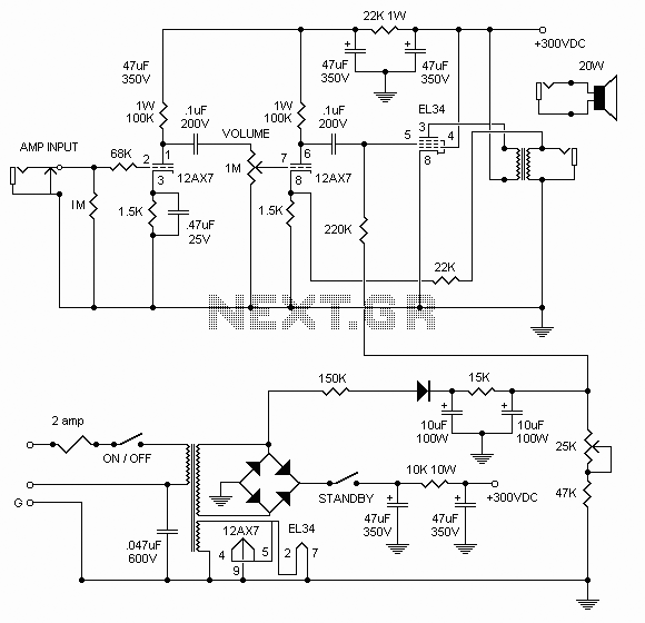
The following diagram illustrates the circuit design of a 20W power amplifier built using the EL34 tube component. The EL34 is a well-known tube that is highly regarded for its performance in power tube amplifiers. The circuit presented is...
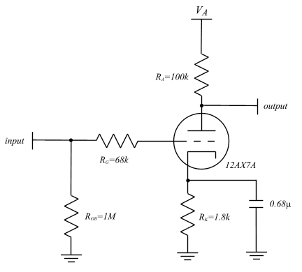
The concept of an AC model for the triode is presented, and the equivalent circuit technique is described. Theoretical calculations for amplifier gain and frequency response are derived and compared to simulation results in the SPICE3 environment, showing good...
Warning: include(partials/cookie-banner.php): Failed to open stream: Permission denied in /var/www/html/nextgr/view-circuit.php on line 713
Warning: include(): Failed opening 'partials/cookie-banner.php' for inclusion (include_path='.:/usr/share/php') in /var/www/html/nextgr/view-circuit.php on line 713