
ASIC stepless dimming lamp circuit
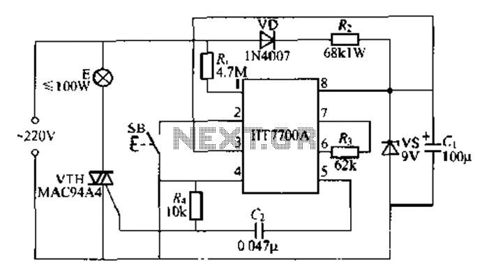
The HT7700A ASIC is an integrated circuit specifically developed for applications requiring precise light dimming capabilities. The device operates on a principle that allows for smooth transitions in brightness, enhancing user experience in lighting control. The single-button interface simplifies operation, enabling users to easily adjust brightness levels across a range of 96 settings.
The zero-crossing detection feature at Pin 1 is crucial for minimizing electrical noise and ensuring efficient power management, as it allows the circuit to switch the load at the moment when the AC voltage crosses zero, thus reducing inrush current and electromagnetic interference. The touch sensor input at Pin 2 allows for intuitive user interaction, where a simple touch can register as a command, contributing to a user-friendly design.
The current input at Pin 3 is essential for the functionality of the touch sensor, as it helps in detecting the presence of a touch and converting it into a corresponding signal for processing. The negative terminal at Pin 4 is a standard connection point for grounding the circuit, ensuring stable operation and minimizing potential noise in the system.
Pin 5's trigger output is designed to control a thyristor, which is a semiconductor device used for switching and controlling power. This allows the HT7700A to effectively manage the power delivered to the lighting system, facilitating the dimming function.
Pins 6 and 7 are dedicated to oscillation signal outputs, which are critical for the internal timing and control functions of the ASIC. These oscillation signals are generated based on external resistor values, which can be adjusted to influence the performance characteristics of the dimming function. Lastly, Pin 8 serves as the positive terminal for the power supply, providing the necessary voltage for the operation of the ASIC.
Overall, the HT7700A ASIC is a sophisticated solution for modern lighting applications, combining ease of use with advanced electronic features to achieve efficient and effective light dimming.Is using a dimmer HT7700A ASIC production keyed stepless dimming lights, make use SB single button control, dimming the brightness has 96 changed. HT7700A scale using CMOS process is made using standard D1P-S-pin package. Preparation of the pin cylinder functions as follows: The first O feet zC alternating current zero-crossing detection signal terminal; first feet SFNSI // KEY as a touch sensor / key signal input terminal; first feet FB when touch input signal current fed ; first leg V ;., Power source negative terminal; first feet IRIC, trigger output for triggering the thyristor;. The first and foot OSC2 OSC1 oscillation signal output, respectively, an input terminal, an external resistor F 62kn first feet v.
., Power source positive terminal.
Related Circuits
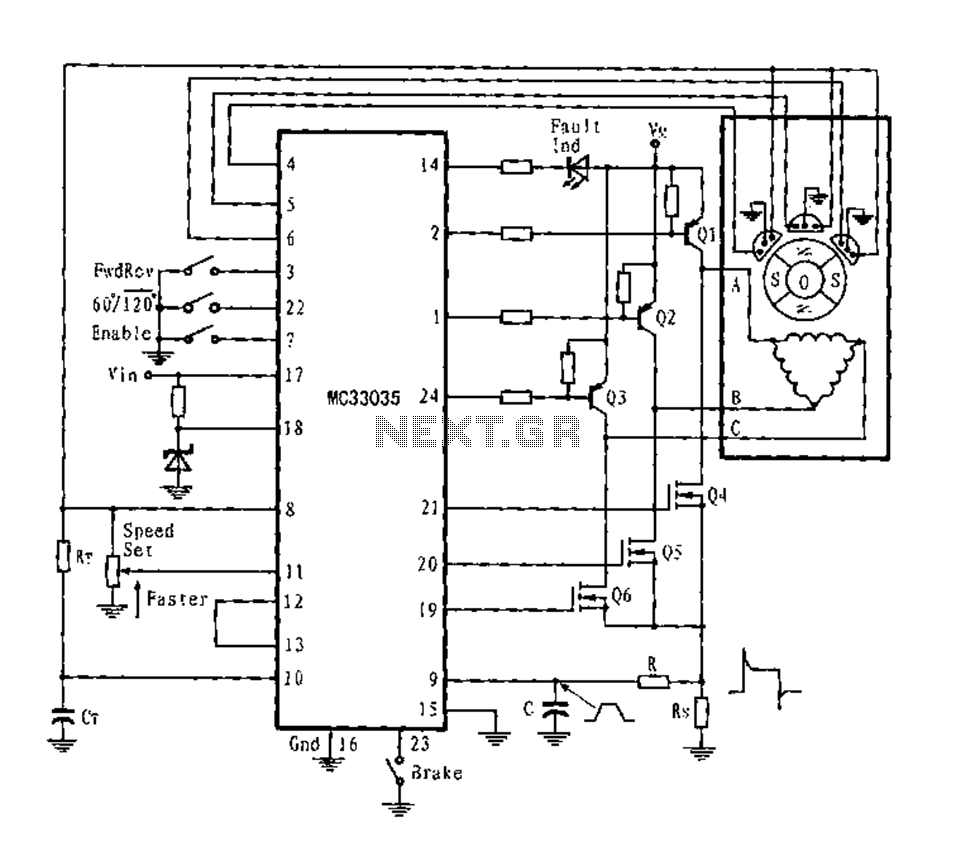
The application circuit is a three-phase full-wave six-step driving circuit for an open-loop motor controller. It features a power switching transistor of the Darlington type, specifically PNP, while the lower power switching transistors are N-channel power MOSFETs. Each device...
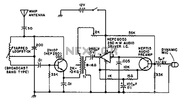
A circuit diagram of the T1 is a low-impedance output transformer, featuring a 5000-8 ohm resistor. The T1 low-impedance output transformer is designed to match the output of audio amplifiers to the impedance of loudspeakers, ensuring optimal power transfer and...
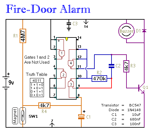
This circuit provides an alert when a door that should remain closed is left open. It is designed to be attached to a fire door, allowing normal passage. If the door remains open for more than 30 seconds, a...
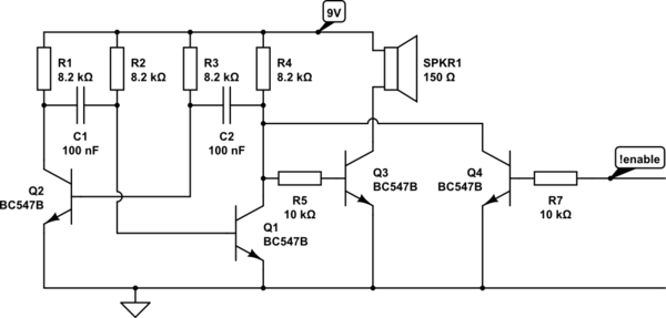
Any ideas? Is this circuit going to be standalone? Is there any other circuitry around it, perhaps a microcontroller? What circuitry does the timing device contain, or does it even contain electronics? Abdullah Kahraman Mar 22, '13 at 18:10....
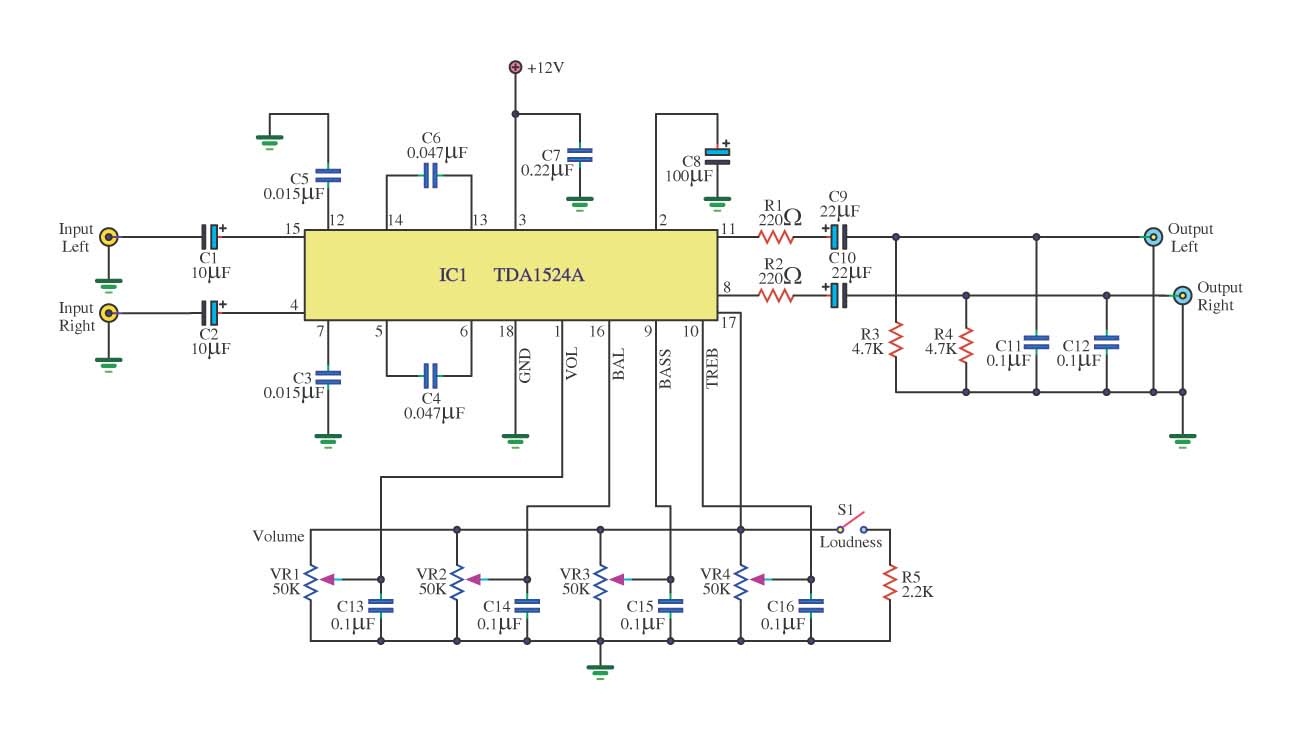
This is a simple tone control circuit using the TDA1524A, which is a key component in this IC chip diagram from Philips. The circuit allows for tone control adjustments such as bass, treble, and balance, enabling users to fine-tune...
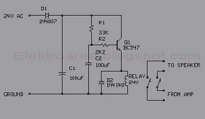
This circuit was designed for an audio amplifier project to control the speaker output relay. The primary function of this circuit is to manage the relay that activates the speaker output in the audio amplifier. The circuit introduces a...
Warning: include(partials/cookie-banner.php): Failed to open stream: Permission denied in /var/www/html/nextgr/view-circuit.php on line 713
Warning: include(): Failed opening 'partials/cookie-banner.php' for inclusion (include_path='.:/usr/share/php') in /var/www/html/nextgr/view-circuit.php on line 713