
Amplifier Output Delay with Relay Schematic Diagram
This circuit is structured around a few key components: capacitors C1 and C2, resistors R1 and R2, and transistors Q1 and Q2, along with a relay. Capacitor C1 serves as a primary filter capacitor, stabilizing the input voltage and ensuring smooth operation during power-up. Capacitor C2 is critical for creating the delay; it charges slowly, allowing time for the amplifier to stabilize before the speakers are connected. Resistor R1 controls the charging rate of C2, while resistor R2 facilitates the discharge process when power is removed, ensuring a rapid disconnect of the speakers.
Transistor Q1 functions as a switch that responds to the voltage across C2. As C2 charges, the base-emitter voltage of Q1 increases, turning it on and allowing current to flow. This, in turn, affects the operation of Q2, which is responsible for driving the relay. The relay itself acts as an electromechanical switch, providing a physical connection to the speakers only when the circuit conditions are met.
The design ensures that the speakers are not subjected to power surges or noise during the amplifier's turn-on and turn-off phases, enhancing the overall audio experience. The delay mechanism is crucial in audio applications, where abrupt changes in signal can result in audible pops or thumps, which could be damaging to both the speakers and the listener's experience. The circuit's simplicity and effectiveness make it an ideal solution for audio amplifier projects requiring speaker protection.This is a minimal circuit which I built to individual of my audio amplifier projects to control the presenter output relay. The end of this circuit is to control the relay which turns on the speaker output relay within the audio amplifier.
The impression of the circuit is time lag around 5 seconds ofter the power up until the speakers are switched to the amplifier output to circumvent grating pound sound from the speakers. an added appear of this circuit is so as to is disconnects the orator just now once the power within the amplifier is finish inedible, so avoiding every now and then nasty sounds as soon as you trip the equipments inedible. Followed by power is functional to the power input of the circuit, the categorical stage of AC voltage charges C1.
Then C2 starts to charge little by little through R1. while the voltage in C2 rises, the emitter output voltage of Q1 rises concurrently with voltage on C2. as the output voltage of Q2 is anticyclone an adequate amount of (typically around 16. 20V) the relay goes to on state and the relay witches associate the speakers to the amplifier output.
It takes typically around 5 seconds in the same way as power up until the relay starts to conduct (next to absolute epoch depends on the size of C2, relay voltage and circuit input voltage). as the power is switched rotten, C1 force not tied up it`s energy quite quickly. and C2 will transpire charged quite quickly through R2. into excluding than 0. 5 seconds the speakers are disconnected from the amplifier output. You are reading the Circuits of Amplifier Output Delay with Relay And this circuit permalink url it is
🔗 External reference
Related Circuits

A high-power and efficient 100W power amplifier electronic project can be designed using the STK404 audio power amplifier hybrid ICs. These ICs consist of optimally designed discrete component power amplifier circuits that have been miniaturized using SANYO's unique insulated...
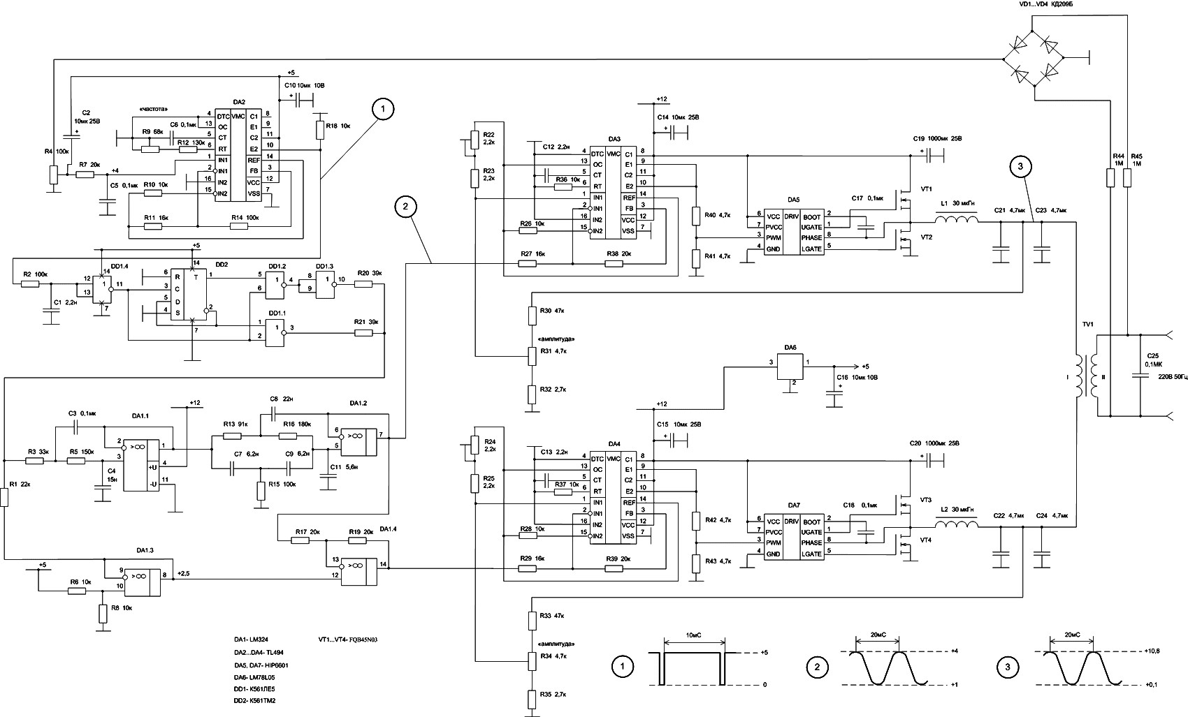
In DA3, DA5, VT1, and VT2, the first channel of the VLF Class D amplifier is assembled. The second channel is constructed using DA4, DA7, VT3, and VT4. Antiphase sine waves in the VLF range are formed at the...
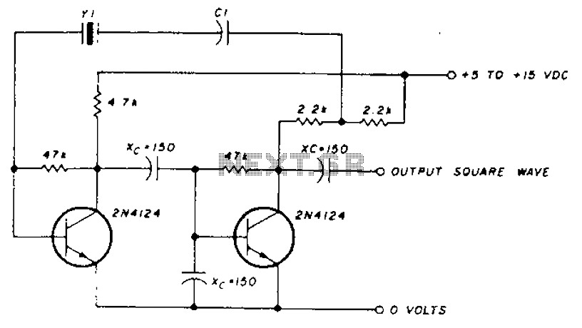
A transistor in series with capacitor C1 can be utilized to adjust the oscillator output frequency. The frequency may vary with changes in capacitance ranging from 20 pF to 0.01 µF, or as determined by the tuning capacitor. The...
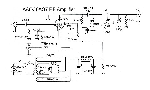
The input coupling capacitor allows the input signal to pass through to the grid of the tube while preventing the input source from potentially shorting the grid bias to ground. If the grid bias were shorted out, the 6AG7...
A unit that is often very useful for isolating two stages in sound circuits. This circuit includes an amplification unit with a gain of X1. Total negative feedback is not employed; instead, only local feedback is used, resulting in...
This schematic requires clarification. It is assumed that pin 2 is connected by a wire to pin 6, although this connection appears to be unclear. The circuit in question involves a schematic where pin 2 and pin 6 are interconnected....