
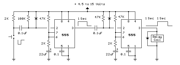
amplifier timer
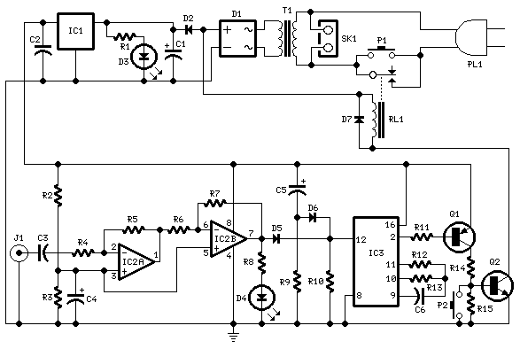
This circuit operates as an automatic power management system for devices that rely on audio signals for activation. The core components include operational amplifiers, transistors, and a relay, which work in concert to ensure that the connected devices are only powered when necessary.
The audio signal is processed by IC2, which consists of two operational amplifier stages configured to boost and square the incoming signal. This amplification is crucial for detecting even the faintest audio signals. The LED D4 serves as an indicator, providing visual feedback that the circuit is active and monitoring the input signal.
The timing function is handled by IC3, which is likely a timer IC such as the 555 timer or a microcontroller. It is configured to count the duration of the absence of an audio signal. The reset mechanism, triggered by the brief illumination of LED D4, ensures that any momentary presence of an audio signal will prevent the timer from reaching its 15-minute threshold.
The transistors Q1 and Q2 are configured as a switch to control the relay. When the timer expires and pin 2 of IC3 transitions to a high state, both transistors turn off, which deactivates the relay and cuts power to the connected appliances. This feature is particularly useful for energy conservation, preventing appliances from remaining powered when not in use.
The inclusion of C5 and R9 provides a reset function for IC3, ensuring that the timer starts fresh each time the circuit is powered on. The manual switch P2 allows the user to immediately turn off the circuit, offering flexibility in operation.
For applications requiring devices that do not utilize standard mains power, the suggestion to use a double-pole relay switch allows for safe and effective control of power to those devices. This configuration ensures that the circuit can be adapted for various operational requirements, making it a versatile solution for audio-activated power management.This circuit turns-off an amplifier or any other device when a low level audio signal fed to its input is absent for 15 minutes at least. Pushing P1 the device is switched-on feeding any appliance connected to SK1. Input audio signal is boosted and squared by IC2 A & B and monitored by LED D4. When D4 illuminates, albeit for a very short peak, IC3 is reset and restarts its counting. Pin 2 of IC3 remains at the low state, the two transistors are on and the relay operates. When, after a 15 minutes delay, no signal appeared at the input, IC3 ends its counting and pin 2 goes high. Q1 & Q2 stop conducting and the relay switches-off. The device is thus completely off as also are the appliances connected to SK1. C5 & R9 reset IC3 at power-on. P2 allows switch-off at any moment. Needing to operate a device not supplied by power mains, use a double pole relay switch, connecting the second pole switch in series with the device`s supply.
🔗 External reference
Related Circuits
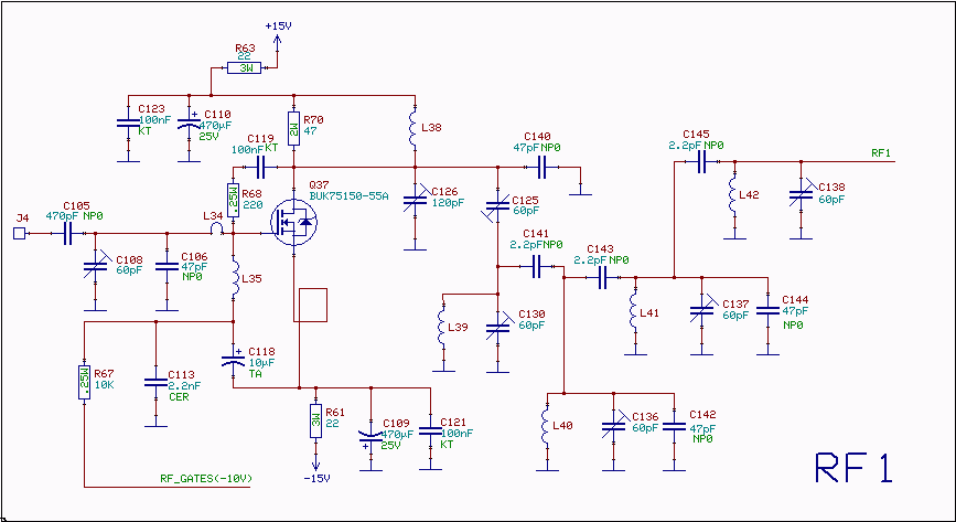
The RF amplifier utilizes noiseless feedback via the drain-gate capacitance, incorporating an inductor in the source lead to achieve the required 90-degree phase shift between the gate voltage and channel current. The RF amplifier is designed to enhance signal strength...
This circuit can be directly connected to CD players, tuners, and tape recorders. It requires the addition of a 10K logarithmic potentiometer (dual gang for stereo) and a switch to accommodate various sources. Proper grounding is crucial to eliminate...
The CMOS 4060 is a 14-bit binary counter; however, only ten of these bits are connected to output pins. The 4060 also includes two inverters, which are connected in series across pins 11, 10, and 9. Together with resistors...

This design circuit outlines a simple, low-cost, and ultra-compact VHF/UHF Low-Noise Amplifier (LNA) that can be implemented using the MAX2664 and MAX2665 devices, which are specifically tailored for VHF/UHF applications. The MAX2664 operates within the UHF frequency range of...
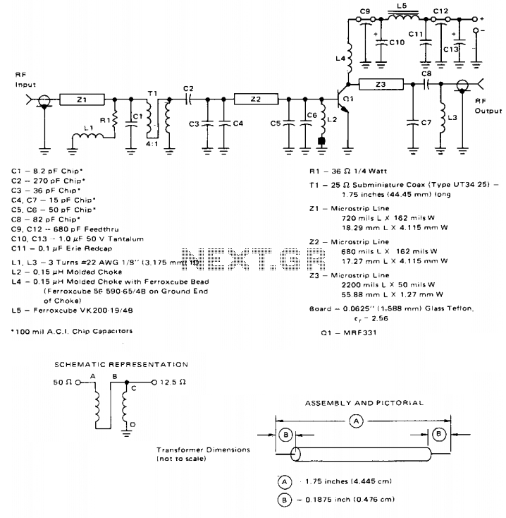
This broadband amplifier operates within the 225-400 MHz military communications band, delivering an RF output power of 10 watts while powered by a 28-volt supply. It is suitable for use as a driver for higher power devices such as...
This toggle circuit utilizes two 555 timers configured as inverters. Pins 2 and 6 serve as the threshold and trigger inputs for the first timer, while pin 5 provides the output. The output at pin 5 will consistently reflect...
Warning: include(partials/cookie-banner.php): Failed to open stream: Permission denied in /var/www/html/nextgr/view-circuit.php on line 713
Warning: include(): Failed opening 'partials/cookie-banner.php' for inclusion (include_path='.:/usr/share/php') in /var/www/html/nextgr/view-circuit.php on line 713