
AmpOP Colpitts Oscilator simulation

The Colpitts Oscillator is a type of electronic oscillator that utilizes a combination of inductors and capacitors to generate oscillations at a specific frequency. The frequency of oscillation is determined by the values of the reactive components in the circuit. In a typical Colpitts configuration, the circuit consists of an op-amp configured for feedback, along with a tank circuit made up of capacitors (C1 and C2) and an inductor (L).
To achieve the desired frequency of 10 MHz, the following parameters must be carefully calculated and implemented:
1. **Component Values**: The frequency of oscillation (f) for a Colpitts oscillator can be calculated using the formula:
\[
f = \frac{1}{2\pi \sqrt{L \cdot C_{eq}}}
\]
where \(C_{eq} = \frac{C1 \cdot C2}{C1 + C2}\) is the equivalent capacitance of the two capacitors in series. It is crucial to select appropriate values for L, C1, and C2 to achieve the target frequency of 10 MHz.
2. **Op-Amp Configuration**: The op-amp should be configured in a feedback loop that ensures the gain is sufficient to sustain oscillations. The gain of the op-amp must be set to at least 3 for the oscillator to start oscillating, which can be achieved through the use of resistors in the feedback path.
3. **Phase Shift Requirement**: The circuit must provide a total phase shift of 360 degrees (or 0 degrees) to satisfy the Barkhausen criterion for oscillation. This is typically achieved by the combination of the reactive components and the op-amp's feedback configuration.
4. **Power Supply and Biasing**: Ensure that the op-amp is powered correctly and that the input and output are properly biased to avoid distortion or clipping of the waveform.
5. **Simulation Parameters**: In a simulation environment, parameters such as the op-amp model, power supply voltages, and load conditions must be accurately set to reflect real-world conditions. Any discrepancies in these settings can lead to deviations in the output frequency.
By addressing these aspects of the Colpitts oscillator design, it is possible to achieve the desired 10 MHz output frequency. If the frequency remains incorrect, further investigation into component tolerances, layout, and simulation settings may be necessary to identify the source of the discrepancy.Hello, I`m trying to simulate a 10MHz Colpitts Oscillator using an OPAMP, but i`m not getting the expected outcome, the frequency is not 10MHz and the .. 🔗 External reference
Related Circuits
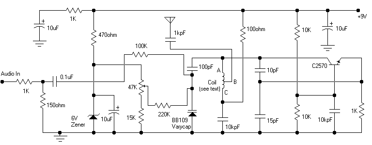
Its frequency depends on the capacitance of the vary cap diode. The center frequency is changed by varying the biasing voltage of the vary cap through the 47K pot. You can use a 75cm telescopic antenna or simply a...
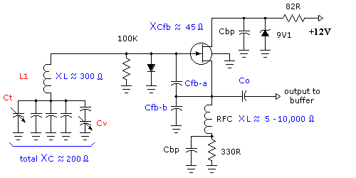
Colpitts oscillators are similar to the shunt-fed Hartley circuit; however, the Colpitts oscillator uses two series capacitors in its LC circuit instead of a tapped inductor. The connection between these two capacitors serves as the center tap for the...
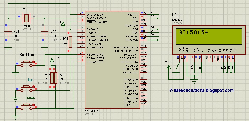
This tutorial on the PIC16F877 microcontroller addresses the question, "How to implement a controllable digital clock using the PIC16F877?" It utilizes the PIC16 simulator for demonstration purposes. The implementation of a controllable digital clock using the PIC16F877 microcontroller involves several...
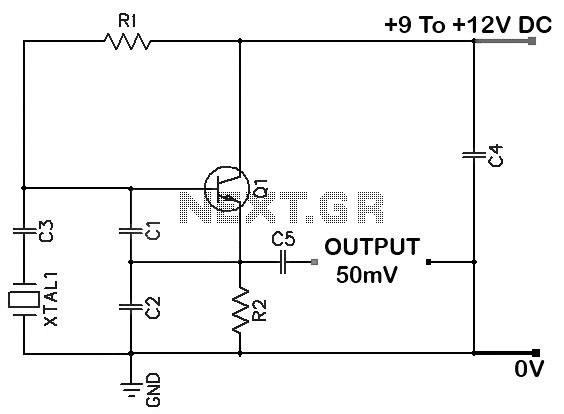
Colpitts 1 MHz to 20 MHz Crystal Oscillator Circuit. This is a simple Colpitts crystal oscillator for frequencies ranging from 1 to 20 MHz. The parts list includes: R1 - 220 kΩ, R2 - 1 kΩ, C1 - 82...
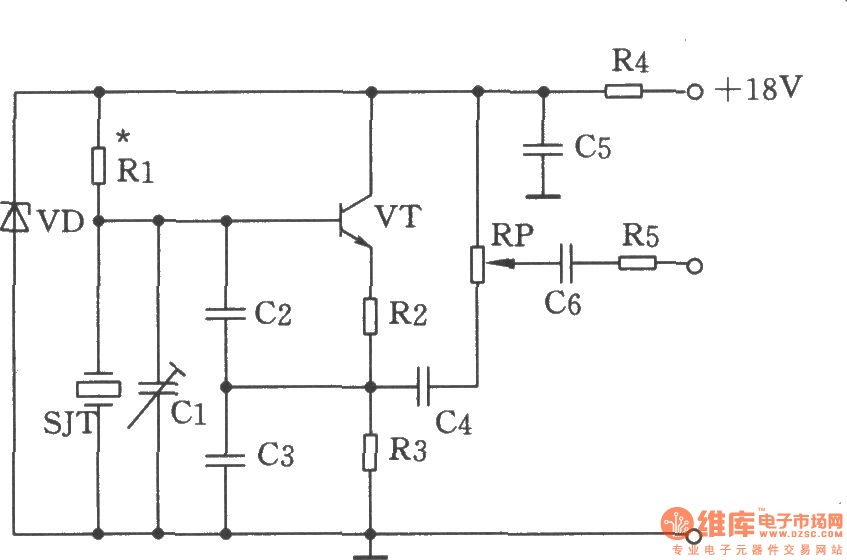
The figure illustrates the Colpitts oscillator circuit, which utilizes a base frequency crystal. The operating frequency is 1499 kHz, with the crystal SJT connected to both ends of capacitors C2 and C3. The emitter divider resistors R2 and R3...
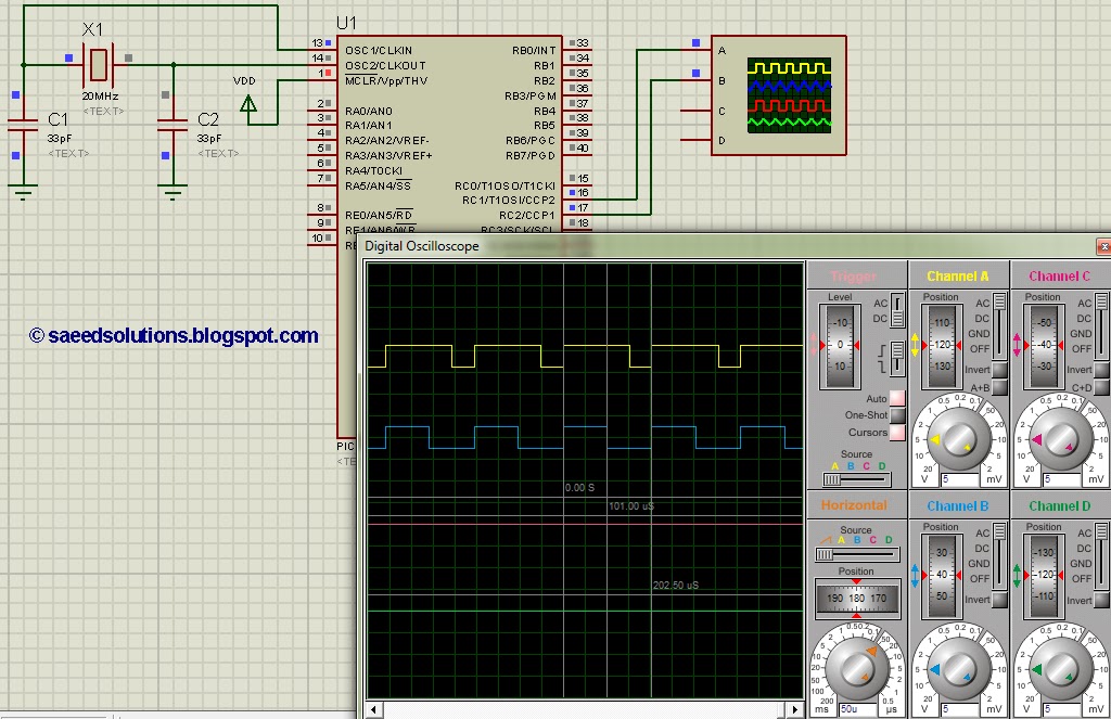
This post addresses the question, "How to create a pulse width modulator using the PIC16F877?" Additionally, the PWM code can be verified using the PIC16 simulator (Proteus). The PIC16F877 microcontroller is widely utilized for creating pulse width modulation (PWM) signals...