
pic16f877 pwm 2 channel code and proteus simulation
The PIC16F877 microcontroller is widely utilized for creating pulse width modulation (PWM) signals due to its built-in features and ease of programming. To design a PWM circuit using the PIC16F877, the following steps and components are typically involved:
1. **Microcontroller Configuration**: The PIC16F877 must be configured correctly to operate in PWM mode. This includes setting the appropriate registers, such as the Timer2 control register, which is essential for generating PWM signals.
2. **Timer Setup**: Timer2 is often used to control the frequency of the PWM signal. The prescaler and postscaler settings need to be adjusted to achieve the desired frequency. The Timer2 register should be set to start counting, and the PWM period is determined by the value loaded into the PR2 register.
3. **Duty Cycle Control**: The duty cycle of the PWM signal can be adjusted by modifying the CCPR1L register, which holds the value that determines the high time of the PWM signal relative to its period. The duty cycle can be calculated as a percentage of the total period, allowing for fine-tuning of the output signal.
4. **Output Configuration**: The output pin for the PWM signal must be configured as a digital output. Typically, this is done by setting the appropriate TRIS register bits to ensure the pin is outputting the PWM signal.
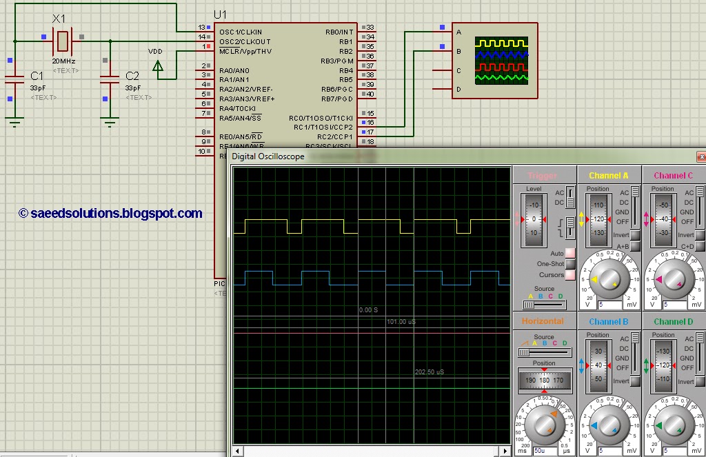
5. **Code Implementation**: The implementation of the PWM code involves writing a program in C or assembly language that initializes the microcontroller, configures the timers, and continuously updates the duty cycle as needed. The code can be simulated using the Proteus software, which allows for real-time verification of the PWM signal and its characteristics.
6. **Simulation and Testing**: After programming the PIC16F877, the circuit can be simulated in Proteus. This simulation will enable observation of the PWM waveform, ensuring that the frequency and duty cycle meet the design specifications. Adjustments can be made in the code or hardware configuration as necessary based on simulation results.
In summary, creating a PWM using the PIC16F877 involves configuring the microcontroller, setting up timers for frequency control, adjusting the duty cycle, and verifying the output through simulation tools like Proteus. This process allows for effective control of devices such as motors, LEDs, and other applications requiring variable power delivery.This post answers the question, ""How to make a pulse width modulator using PIC16F877"" ? Also, using PIC16 simulator (Proteus) you can verify this PWM code.. 🔗 External reference
Related Circuits
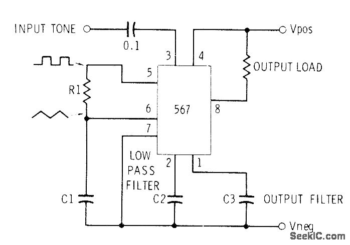
This circuit can be utilized for Touch-Tone decoding as well as for telephone line and wireless control applications using a single audio frequency. The operating center frequency is determined by components H1 and C1. The resistor R1 should be...
The TLE6282G is an H-Bridge and Half Bridge Driver IC designed for high-current DC brush motor applications in PWM control mode. It is suitable for use in injector and valve applications across 12V, 24V, and 42V power networks. This...
This article discusses the 128K EPROM (27C128), which was used in the 1986 to 1989 IROC-Zs equipped with the 1227165 ECM. The purpose is to provide a foundational understanding of binary and hexadecimal systems. Binary numbers consist solely of...
Various techniques demonstrate how enhanced PWM (pulse-width modulation) intensity control can be utilized in LED (light-emitting diode) drivers. PWM intensity control is a widely adopted method in LED driver circuits to regulate brightness levels. This technique involves modulating the width...
A lot of friends ask me a circuit AUDIO MIXER, for various uses. I will begin with a circuit which you can it manufacture, as you want. This you can place in the MODULES of inputs any circuit you...
In this project, we will see how to build a single-channel remote control. It is an easy project to do: by using a pre-assembled radio module, we will get a compact card without sacrificing major performance. The insert function...
Warning: include(partials/cookie-banner.php): Failed to open stream: Permission denied in /var/www/html/nextgr/view-circuit.php on line 713
Warning: include(): Failed opening 'partials/cookie-banner.php' for inclusion (include_path='.:/usr/share/php') in /var/www/html/nextgr/view-circuit.php on line 713