
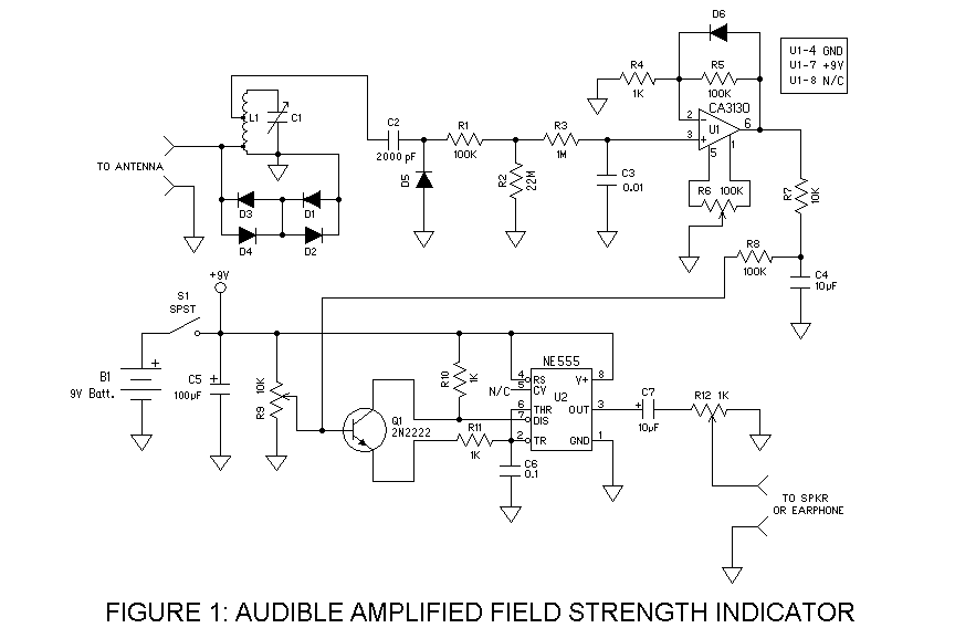
An Audible Field Strength Indicator for Radio Direction Finding
To align the AFSI, the following steps are recommended: First, set R6 fully clockwise, then fully counterclockwise. Turning R6 in one direction should result in a decrease or stabilization of pulse frequency from the speaker, while turning it in the opposite direction should increase the pulse frequency significantly. Starting with R6 adjusted for the slowest pulses, gradually turn R6 until the pulses begin to increase in speed. This careful tuning process is essential for optimizing the performance of the AFSI and ensuring accurate signal detection.An audible field strength indicator (AFSI) lets you listen to changes in radio signal strength so that you can use your eyes to look for concealed antennas. Using inexpensive, easy-to-obtain parts, the following design combines a sensitive amplified field strength detection circuit, and a variable frequency audio oscillator.
Its main features incl ude: Combining the AFSI with a directional antenna, such as the 2-element collapsible delta quad, makes a powerful sniffing tool that lets you home in on a signal source quickly. One caveat: Most field strength meters (including this one) aren`t very selective. That is, they don`t do a very good job of distinguishing between two or more signals on the air at the same time, even when those signals are widely separated in frequency.
Despite the LC tuned circuit resonant at 146 MHz used in this design, the AFSI will respond with surprising sensitivity to paging transmitters at 158 MHz, nearby 440 MHz transmitters, and even cellular phones! So use the AFSI with a certain amount of skepticism in areas where you suspect there could be other RF sources.
A schematic diagram for the AFSI is shown in Figure 1. The signal arriving from the antenna is fed into the tuned circuit formed by L1 and C1. To prevent the antenna system from loading down the tuned circuit, the signal is fed into L1 at a tap located one-half turn from its grounded side. The signal leaving the tuned circuit is taken several turns from the top of L1, also to prevent detuning the tuned circuit.
Diodes D1 to D4 prevent extremely strong signals from overdriving U1. C2 couples the RF from the tuned circuit to D5, which rectifies it, creating a DC voltage that varies with changes in RF signal strength. The DC voltage is fed into a simple integrator (R1-R3 and C3) that smoothes the DC voltage and shapes its decay curve.
The DC level across C3 is connected to the input of a logarithmic DC amplifier formed by U1, D6, and R4-R6. The amplified output goes to R7 and C4, which limit how rapidly the DC voltage can swing. Finally the voltage is coupled by R8 to the input of the variable frequency audio oscillator (Q1, U2, and the R`s and C`s attached to them).
R12 serves as the volume control for the audio output. This field strength indicator is simple enough to be built dead bug ” style, or it can be built on a small circuit board if you prefer. Enclosing the AFSI in a metal chassis is recommended, especially if you plan on using it with a directional antenna.
The shielding provided by the chassis will help prevent signal pickup through routes other than the direction finding antenna. The most difficult part of building this project is getting the LC tuned circuit (L1 and C1) to resonate at the desired frequency.
Winding your own L1 seems to be the best way to go. Wind several inches of #14 copper wire around a size-AAA battery serving as a coil form, and remove the battery from the center of the coil leaving you with an air-core inductor. The number of turns you use will depend on your choice of C1. Six turns is about right for the value of C1 shown above. Be prepared to make some adjustments to L1 in order to get the circuit to resonate. Your efforts will be rewarded by superior signal sensitivity. Once you have the circuit built you are ready to align it. The only essential tool for aligning the AFSI is a weak signal source: a 2-meter transmitter capable of putting out 100 mW or less, or a more powerful transmitter operating into an attenuator or dummy load.
Step #4: Turn R6 fully clockwise, then fully counterclockwise. You should find that turning R6 in one direction results in the pulses coming from the speaker getting slower, or staying the same. Turning R6 in the opposite direction should cause the pulses to get much faster. Starting with R6 turned so that the pulses are slowest, turn R6 slowly until the pulses just begin to get faster.
Step #5: Connect to the AFSI t 🔗 External reference
Related Circuits
In practical applications, a series resistance must always be included. This component serves the dual purpose of limiting the current at pin 7 and smoothing the ON/OFF transitions during standby. In electronic circuits, particularly those involving integrated circuits (ICs) or...
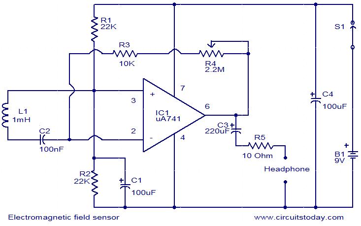
The following circuit illustrates an Electromagnetic Field Sensor Circuit Diagram. This circuit is based on the uA741 integrated circuit. Features: it is used to sense electromagnetic fields. The Electromagnetic Field Sensor Circuit utilizes the uA741 operational amplifier to detect variations...
A radio camera on a model railway is designed to transmit continuously while the train is in motion and to continue transmitting for a few minutes after the train stops. If the train starts moving again after a relatively...
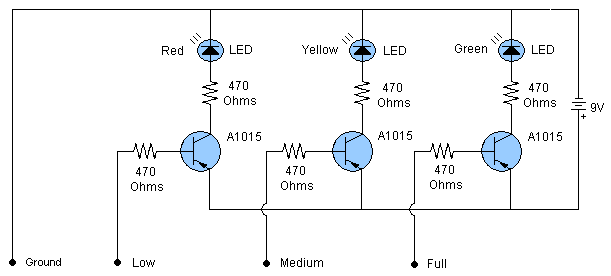
This is a straightforward water level indicator circuit or water level sensor circuit. The circuit is simple to construct and consists of three PNP transistors along with several other components. It serves as a practical solution for detecting the...
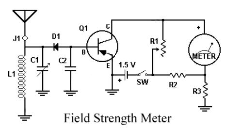
This circuit utilizes a single 1.5V battery. The capacitor C1 must be adjusted for optimal peak reading. To operate the circuit, the transmitter and meter should be turned on. The circuit is designed to operate efficiently with a single 1.5V...
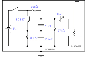
This basic oscillator detects the Earth's magnetic field. A ferrite rod and coil are repurposed from an old Medium Wave receiver, with a small magnet affixed to one end. The device is tuned to a medium wave commercial station...