
2N107 Radio Frequency Field Strength Meter
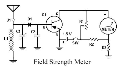
The circuit is designed to operate efficiently with a single 1.5V battery, making it suitable for low-power applications. The use of a single cell simplifies the power supply requirements and enhances portability. The capacitor C1 plays a crucial role in the circuit, as it is responsible for smoothing out voltage fluctuations and ensuring stable readings on the meter.
To achieve the best performance, C1 should be carefully selected and adjusted based on the specific requirements of the application. This may involve varying the capacitance value or tuning the circuit to respond optimally to the signal being measured.
The transmitter component is essential for sending out signals, which may be received by a compatible receiver or measured by the meter. Activation of the transmitter and meter is straightforward; once powered on, they will begin to function as intended.
For practical implementation, attention should be given to the connections and layout of the circuit. Proper grounding and shielding may be necessary to minimize interference and ensure accurate readings. Additionally, component ratings should be verified to ensure compatibility with the 1.5V power supply.
Overall, this circuit design is effective for applications requiring minimal power consumption while providing reliable performance.This Circuit using only a single cell 1.5V battery.C1 need to be adjusted for peak reading. Then, to use it, turn on the transmitter and meter. .. 🔗 External reference
Related Circuits
The circuit consists of an oscillator with variable frequency, a frequency divider, and a measurement stage. The oscillator is based on an inverter from a 74HC14 and generates a frequency that is inversely proportional to the capacitance of the...

A radio camera on a model railway should transmit constantly while the train is moving and continue transmitting for a few minutes after the train stops. The design of a radio camera system for a model railway requires careful consideration...

The LM331 is a precision voltage-to-frequency converter developed by National Semiconductors. This integrated circuit (IC) has various applications, including analog-to-digital conversion, long-term integration, voltage-to-frequency conversion, and frequency-to-voltage conversion. Its wide dynamic range and excellent linearity make it suitable for...
The primary motivation for utilizing battery power for trains is to eliminate the need for track cleaning and wiring. Track maintenance can pose significant challenges. Incorporating radio control into a battery-powered system enhances command control, an advantageous feature. In...
This digital thermometer indicates the temperature measured with an NTC using 7 LEDs. The circuit works using an opamp, the well-known 741, which amplifies the voltage difference between its plus and minus input. This amplification (sensitivity) can be set...
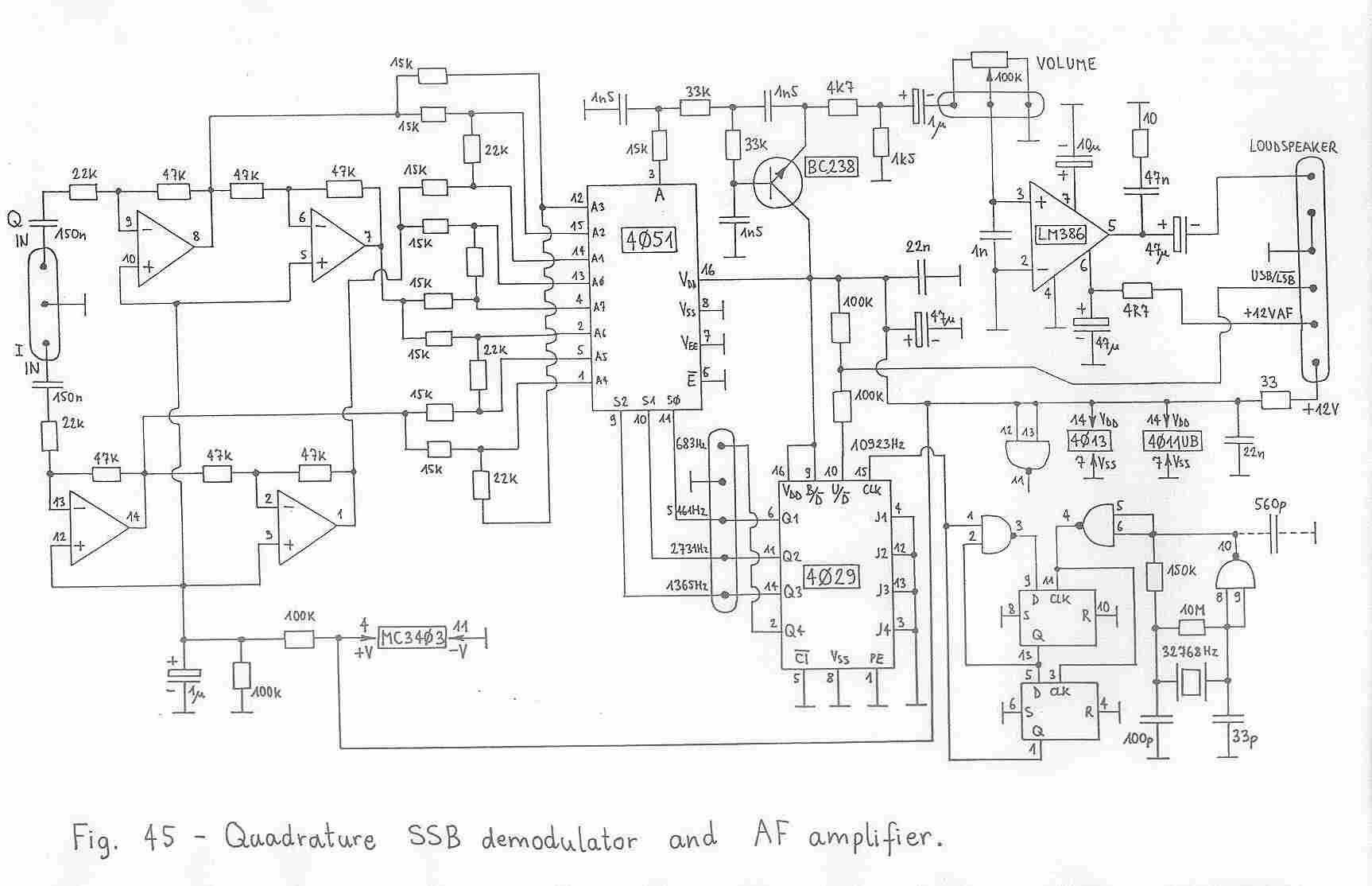
This article is a local and enduring copy derived from replica sites. It appears to have undergone significant revisions in 2006, leading to the disappearance of the original version. When considering SSB transceivers, the primary question is whether it...