
water level indicator
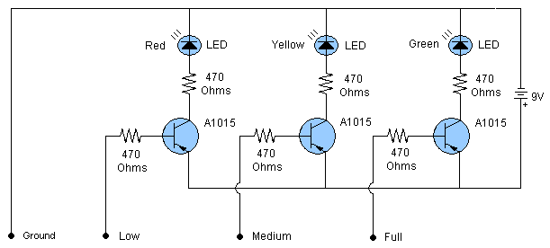
The water level indicator circuit operates by utilizing three PNP transistors, which function as switches to control the LEDs based on the water level detected by the probes. The probes are typically made of conductive materials and are positioned at specific heights within the tank: the low probe is placed at the minimum acceptable water level, the medium probe is set at an intermediate level, and the full probe is located at the maximum capacity of the tank.
When the water level rises to the height of the low probe, it completes the circuit, allowing current to flow through the corresponding PNP transistor. This activation turns on the LED associated with the low level, providing a visual indication that the water level is low. Similarly, when the water level reaches the medium probe, the medium-level LED is illuminated, indicating that the water level is adequate but not full. Finally, when the water level touches the full probe, the full-level LED lights up, signaling that the tank is full.
The circuit's design ensures that only one LED is lit at a time, preventing confusion regarding the water level status. This is achieved through the arrangement of the transistors, where each transistor is responsible for controlling a specific LED based on the state of the probes. Additionally, the ground probe, which is essential for the operation of the circuit, must be securely connected to the bottom of the tank to establish a complete circuit for the sensor operation.
In summary, this water level indicator circuit is an efficient and effective solution for monitoring water levels in various applications, ranging from household water tanks to industrial reservoirs. Its simplicity in design and functionality makes it accessible for both hobbyists and professionals in the field of electronics.This is a simple water level indicator circuit or water level sensor circuit. The circuit is very easy to build and contains only three PNP transistors and some other components. This is a very useful circuit to detect the level of water in the tank. The circuit is using three colors LEDs which will indicate low, medium and full level of water in the tank. The three probes (Low, Medium, Full) are shown in the circuit to attach on desired levels in the tank. The ground probe should be attached at the bottom of the water tank. 🔗 External reference
Related Circuits
The design involves creating a circuit and programming for a stepper motor controller, developing a speed-controlled DC motor circuit for the propulsion system of the project, and designing a navigation system using a MEMS accelerometer circuit. This section deviates...
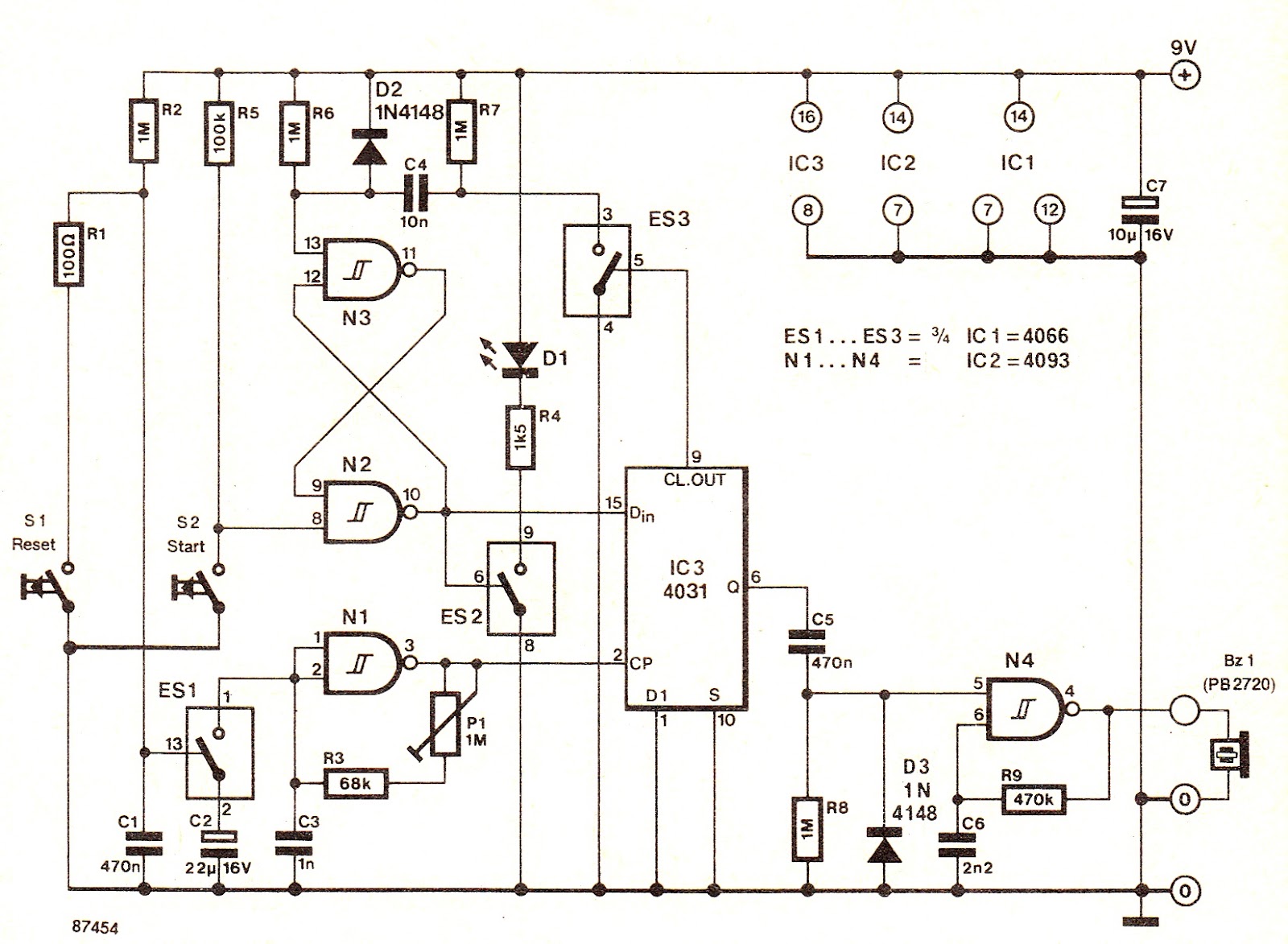
The electronic switch ES1 connects the frequency-determining capacitor to the input of clock oscillator N1. The logic level present at the Dm terminal of the integrated circuit is shifted to output Q at a speed defined by P1, allowing...
This is a straightforward schematic of an amplifier and filter. The circuit primarily features an LM124 operational amplifier configured in an inverting setup. The schematic illustrates a basic audio amplifier and filter circuit utilizing the LM124 operational amplifier. The LM124...
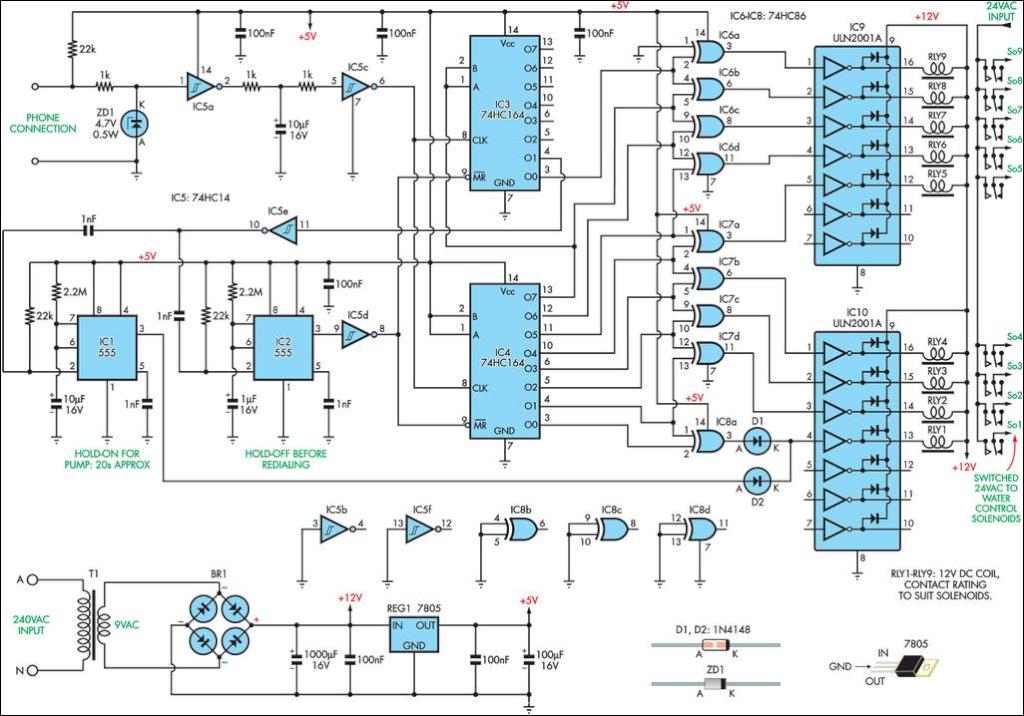
This remotely controlled watering system is both inexpensive and easy to expand. It is designed to operate in conjunction with a conventional watering timer. The remotely controlled watering system is an innovative solution for automated irrigation, allowing users to manage...
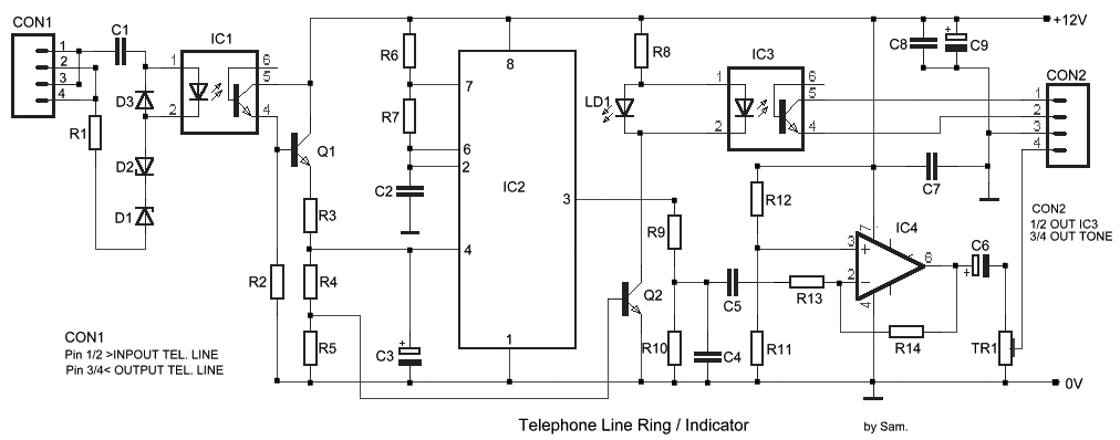
The circuit has been designed for telephone apparatus to indicate an incoming call as it rings using an LED for visual indication. BC550, an NPN general-purpose transistor, is utilized in the design. The circuit operates by detecting the ringing voltage...
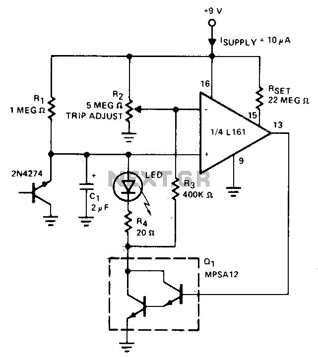
The indicator flashes an LED when the battery voltage drops below a certain threshold. The 2N4274 emitter-base junction serves as a zener diode, establishing approximately 6V on the L161's positive input. As the battery voltage decreases, the output of...