
An AVR microcontroller based Ethernet device

The ENC28J60 Ethernet controller is a robust solution for integrating Ethernet capabilities into small-scale projects. Its design simplifies the complexities traditionally associated with Ethernet interfaces. The chip's integration of MAC, PHY, and Tx/Rx functionalities reduces the overall component count, making it not only cost-effective but also space-efficient. The 28-pin DIP package is particularly advantageous for hobbyists and developers who often work with prototyping boards.
In the described circuit, the relay connected to CONN3 acts as a switch for external devices, allowing for control over various applications such as lighting or heating systems. The inclusion of diode D1 serves as a flyback diode, preventing back EMF generated by the relay coil from damaging the microcontroller and other components. This protective measure is critical for maintaining the longevity and reliability of the circuit.
For projects requiring more advanced functionality, the reserved "IO-ports" and "Analog-IN" connectors provide flexibility for future enhancements, such as integrating additional sensors or actuators. The use of UDP for communication allows for lightweight data transmission, suitable for applications where real-time interaction is not critical. The potential for implementing TCP would enable more complex interactions, such as remote access through web interfaces, significantly expanding the usability of the device.
The power requirements and thermal management considerations are also important aspects of the design. The LM2937-33 voltage regulator must be adequately heatsinked if the input voltage exceeds 5V, which is a common scenario in many applications. This ensures stable operation under varying load conditions.
Overall, the ENC28J60 Ethernet chip, combined with careful circuit design, provides a powerful platform for developing networked devices with minimal complexity and maximum flexibility. The outlined project serves as a foundational step toward exploring the capabilities of this chip in various applications.Ethernet has traditionally been a quite complex interface. All Ethernet chips until today had 100 pins or more, where difficult to find in small quantities and difficult to use from a small microcontroller with little memory. Microchip has changed the world with their new ENC28J60 Ethernet chip! This opens a whole world of completely new applicati ons. You can easily build small devices which can be spread all over the house and simply connected to ethernet. The ENC28J60 from Microchip is a fantastic chip. It has Tx/Rx, MAC and PHY in one small chip. There are very few external parts. Basically just a crystal and an Ethernet transformer, aka magnetics. All this comes in an convenient 28-pin DIP package. Easy to solder and perfect for hobby applications. The microcontroller can then control any hardware you like: You can attach some sensor (light, temperature), you can switch on an off something you can attach a LCD display, etc.
In this first article we will build a generic hardware with lots of IO interfaces and analog to digital converter inputs. We will however only control a small relay to switch on or off something. In later articles we can then use the same hardware and do more complicated things. The main purpose is to show here the circuit diagram and explain the software. We use a UDP application to send commands to the microcontroller. Those commands will then cause the microcontroller to switch on or off the relay. It think it will be possible to even implement TCP. The current UDP software is less than 3k bytes and that is not even half of the memory on an Atmega88.
TCP would then allow us to control the device via a web browser. I have however not tried it yet. Here is the circuit diagram. Most of it is very straight forward and standard for the ENC28J60. The polarity of LED-B is important as it determines the duplex operation of the chip. Standard Half-duplex is what makes most sense for a device which will send and receive only rather little traffic. Figure 2: Circuit diagram (click on the drawing to get a printable pdf version). The circuit diagram of the previous hardware version can be found in the download section A relay can be connected to connector CONN3.
Note the diode D1. It is not useless and it is not the wrong way round in the circuit diagram even though it looks like that. It is there for those who plan to connect a small 6V relay on that output. It protects the whole circuit against the possibly very high voltages which can be induced by the coil of a relay.
If you use a relay with a large coil then you should also add a resistor in parallel to the relay (e. g 1K or 2. 2K). The diodes have a finite response time and such a resistor will prevent the voltages to raise too fast before the diode cuts them.
If you plan use 9V raw-DC (or maybe more) in combination with a 6V relay on CONN3 then you can add a small resistor (e. g 33 Ohm, you have to experiment) in series to the relay to compensate for the higher voltages. The connectors named "IO-ports" and "Analog-IN" are not used for now. They are meant for future functionality which will be described in later articles. We will only use CONN3 in this project. Ethernet requires quite high currents because it can be used with rather long cables. The above circuit consumes about 200mA at 3. 3V. The LM2937-33 needs therefore cooling if the supply voltage is more than 5V (on Raw-DC-In). A small piece of aluminium is normally enough. The ENC28J60 requires a transformer with a turn ratio of 1:1 certified for 10base-T. There are some very nice RJ45 connectors called "Magjack" which have already integrated magnetics and optionally integrated LEDs.
In addition you need a small filter coil (L1 in the schematic). A 5mm ferrite bead with 5-7 turns of thin wire seems to work well. The diode D1 was incorrectly connected against GND instead of Vdd. Interestingly nobody noticed that fault. The wrongly connect 🔗 External reference
Related Circuits
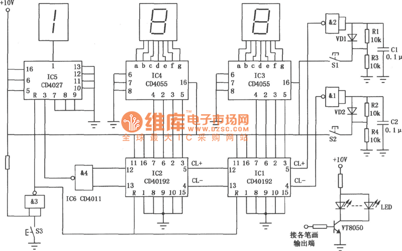
The circuit for the ball game scoring device is depicted in the accompanying image. This device records and displays the performance of a ball game. The first Nixie tube has two states: it can either be off or display...
AVRtools features an intuitive graphical user interface and utilizes predefined function blocks. It provides a wide array of basic functions, including timers, counters, logic operations, and analog signal processing. Additionally, it includes function blocks for sending SMS messages over...

The Edge Avoider Robot (EAR) is a mobile device that detects and avoids areas where there is no surface beneath it. The Edge Avoider Robot (EAR) operates using a combination of sensors and microcontroller technology to navigate its environment effectively....

Freescale Semiconductor has introduced what it claims to be the industry's first tire pressure monitoring system (TPMS) featuring a capacitive pressure sensor designed for ultra-low power consumption and precise sensing. "By utilizing capacitive sensor technology, we achieve low power...
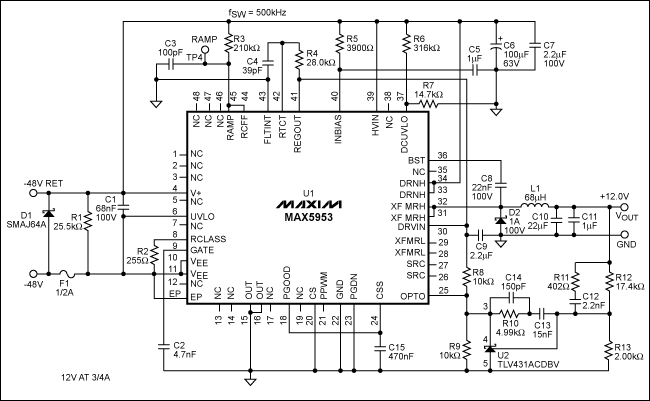
The MAX5953A offers a straightforward, cost-effective, and comprehensive non-isolated power integrated circuit (IC) solution for Powered Devices (PD) in Power-over-Ethernet (PoE) systems. The MAX5953A is designed to facilitate the implementation of Power-over-Ethernet applications by providing an efficient means of...
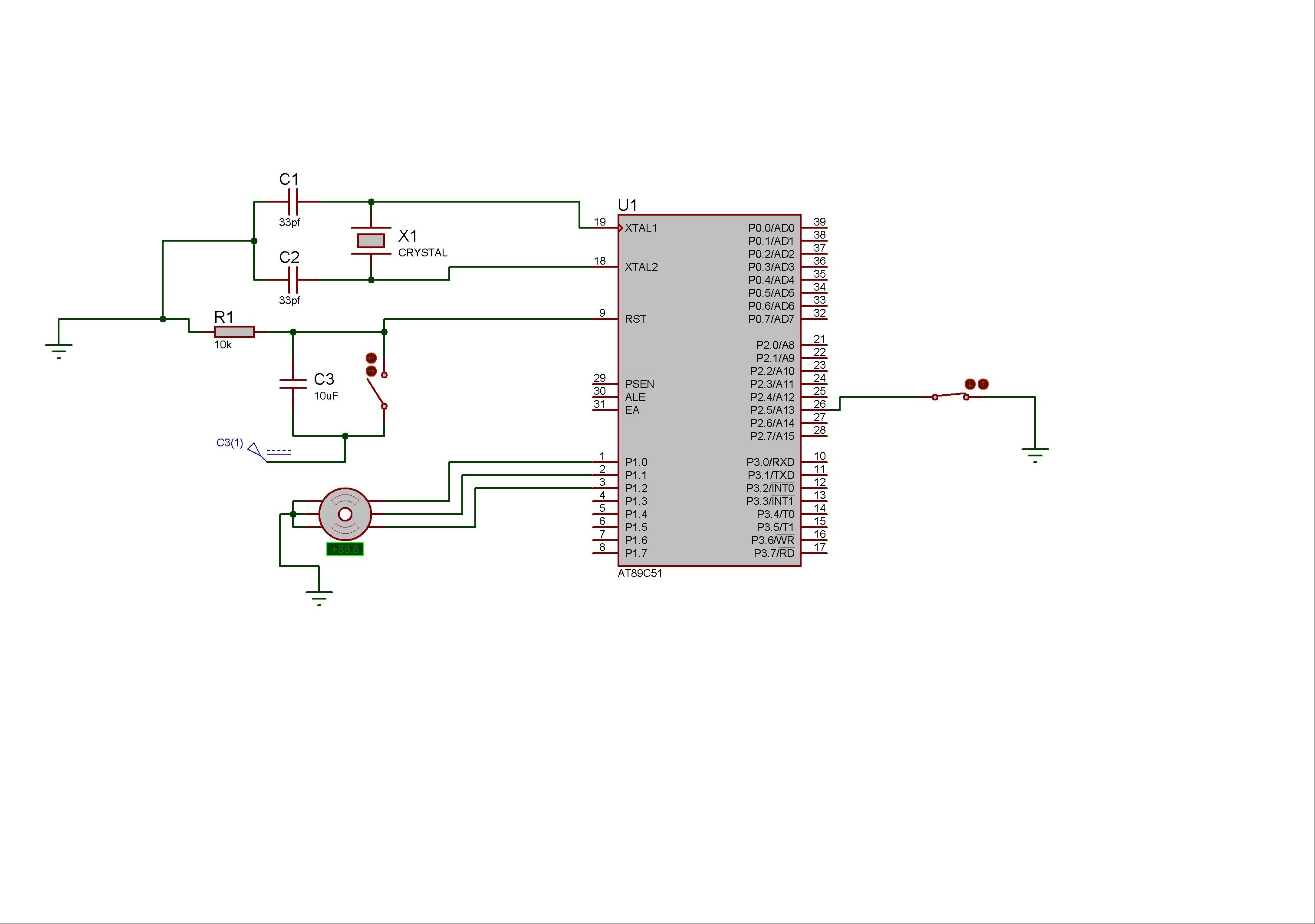
Stepper motors consist of a permanent magnet rotating shaft, known as the rotor, and electromagnets on the stationary part that surrounds the motor, referred to as the stator. One complete rotation of a stepper motor is illustrated. At position...