
Bridging Touch Plate Sensor Circuit
The circuit comprises two 567 tone decoders, which are integrated circuits designed for frequency detection and generation. The first decoder, U1, operates in oscillator mode, generating a specific frequency signal. This signal is then fed into the second decoder, U2, which is configured to detect the frequency produced by U1. The connection points TP1 and TP2 serve as test points that link the output of U1 to the input of U2, enabling U2 to receive and process the signal.
When the signal from U1 reaches U2, pin 8 of U2 transitions to a low state. This low signal indicates that the detected frequency matches the expected frequency set in U2, thus confirming the successful operation of the oscillator. The output of U2 is connected to the base of transistor Q2, which acts as a switch. When U2's output goes high, it turns Q2 on, allowing current to flow through the collector-emitter path.
As a result, the activation of Q2 drives the output high, which can be used to power additional components or indicators in the circuit. In this case, the output is used to illuminate LED1, providing a visual indication that the circuit is functioning correctly. The LED serves as a simple yet effective means of confirming that the tone detection has occurred and that the system is operational.
Overall, this circuit design effectively demonstrates the use of tone decoders for frequency generation and detection, along with a straightforward mechanism for output indication through LED illumination. The interaction between the oscillator and detector showcases the utility of the 567 ICs in various electronic applications, particularly in tone generation and signaling systems. In This circuit, two 567 tone decoders are used. One is an oscillator, the other is a detector. Bridging TP1 and TP2 causes U2 to receive Ul`s signal, which causes pin 8 of U2 to go low. This action lights LED1 and drives the output of Q2 high. 🔗 External reference
Related Circuits

The wire speed DC motor consistently receives approximately 20 volts, irrespective of the switch position on the nozzle handle. The switch has been tested with an ohmmeter and functions properly. Even after disconnecting the switch from the circuit board,...

If the AC supply is 220 volts, which resistor should be replaced and with which one? Since 220V is twice that of 110V, the resistance value needs to be doubled accordingly. It is suggested to replace the 9.1kΩ resistor...
The triac is expected to activate and illuminate the light at nearly 100% brightness; however, it does not turn on at all. If the gate is continuously triggered (i.e., a constant voltage is applied to the gate), the light...

This circuit provides an intermittent siren output with an automatic reset function. It can be manually activated using a key switch or a concealed switch, and it can also be configured to engage automatically when the ignition is turned...

A four-stage FM transmitter circuit diagram utilizes four radio frequency stages: a VHF oscillator designed around the BF494 transistor (T1), a preamplifier based on the BF200 transistor (T2), a driver built with the 2N2219 transistor (T3), and a power...
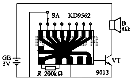
The KD9562 music octave circuit is an analog sound circuit capable of producing various sound effects including rifle shots, space shots, game console sounds, dual-tone doorbells, bomb explosions, machine gunfire, and ambulance sirens. The main electrical parameters are as...