
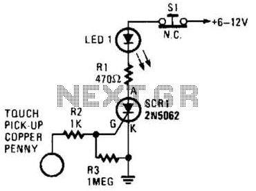
Touch Switch Circuit
The circuit described operates as a touch-sensitive switch using a combination of operational amplifiers and a triac-based lamp driver. The primary component, U1, is responsible for detecting the touch input and controlling the output states. When the touch-on contacts are bridged, a low signal at pin 6 of U1 indicates activation. This results in a high output at pin 4, which splits into two distinct paths.
The first path involves the output being applied to pin 2 of U1. This action leads to a low output at pin 3, which is then fed back to pin 5 of U1, ensuring that the operational amplifier latches in a high output state. This feedback mechanism is crucial for maintaining the output state even after the initial touch is removed.
The second path utilizes the output from U1 to drive transistor Q1. When Q1 is activated, it energizes U2's internal LED. The illumination of the LED triggers U2's light-sensitive triac-driver, which is designed to control larger loads. This triac driver feeds gate current to TR1, which is a triac responsible for switching on the connected lamp (L1).
The circuit's operation can be toggled off by bridging the off contact, which causes the output from U1 to switch states. The output at pin 3 goes high, resulting in a low output at pin 4, effectively turning off the lamp. This design allows for both touch activation and deactivation of the lamp, providing a user-friendly interface for controlling lighting based on touch input. The use of operational amplifiers, transistors, and a triac driver exemplifies a robust approach to creating a touch-sensitive control system for lighting applications. When the touch-on contacts are bridged, pin 6 of Ul-b goes low, which forces its output (the set output) at pin 4 to go high. That high divides along two paths; in one path, the output is applied to pin 2 of Ul-a, which causes its output at pin 3 to go low.
That low is, in turn, applied to pin 5 of Ul-b, which latches the gate in a high output state. In the other path, the output of Ul-b is used to drive Ql. When Ql turns on, U2`s internal LED lights, which turns on its internal, light-sensitive, triac-driver (diac) output element. The triac driver feeds gate current to TR1, causing it to turn on, and light the lamp (11). When the off contact is bridged, IJl-a`s output switches and latches high, causing Ul-b`s output to go low, turning off the lamp. 🔗 External reference
Related Circuits
The circuit operates based on a desired temperature setting. It can be utilized for various applications, such as turning on a fan at a specified temperature or activating an emergency temperature alarm. The power supply for the circuit can...
This is a simple mains power failure alarm circuit that activates an alarm when the mains supply is lost. Unlike many similar circuits, this design does not require a backup power source, such as a battery, to operate the...
The bi-directional sequencer employs a 4-bit binary up/down counter (CD4516) and two "1 of 8 line decoders" (74HC138 or 74HCT138) to create the well-known "Night Rider" display. A Schmitt Trigger oscillator generates the clock signal for the counter, with...
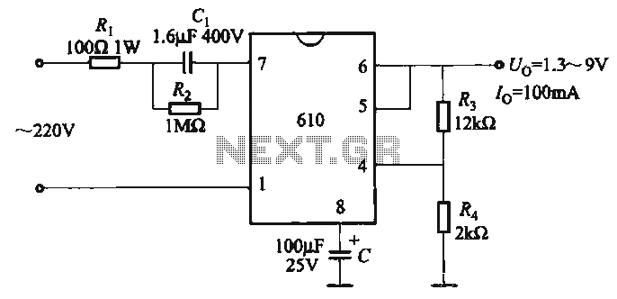
The output voltage can be calculated as follows: U = 1.3 (1 + R3 / R4) (V), where R3 and R4 are part of an adjustment potentiometer, allowing for a continuously adjustable output voltage. The described circuit involves a voltage...
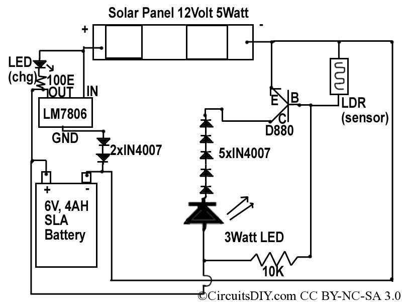
This document discusses a simple solar LED circuit. Solar panels range from 12 volts and 3 watts to larger sizes. To store energy, a 12-volt battery is required. The preferred choice is a sealed lead-acid (SLA) sealed maintenance-free (SMF)...
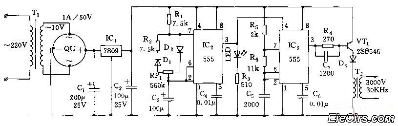
Adjust the RP1 to modify the pulse duty cycle of IC2, which in turn alters the pulse oscillation time of IC3. This regulation allows for the control of ozone generation time, effectively changing the concentration of ozone in the...
Warning: include(partials/cookie-banner.php): Failed to open stream: Permission denied in /var/www/html/nextgr/view-circuit.php on line 713
Warning: include(): Failed opening 'partials/cookie-banner.php' for inclusion (include_path='.:/usr/share/php') in /var/www/html/nextgr/view-circuit.php on line 713