
How to Hack Your Sifteo Base for Bigger Audio
The Sifteo Base audio circuit is designed to provide audio output for interactive gaming experiences. The circuit typically includes an audio amplifier, a digital-to-analog converter (DAC), and various passive components to ensure optimal sound quality.
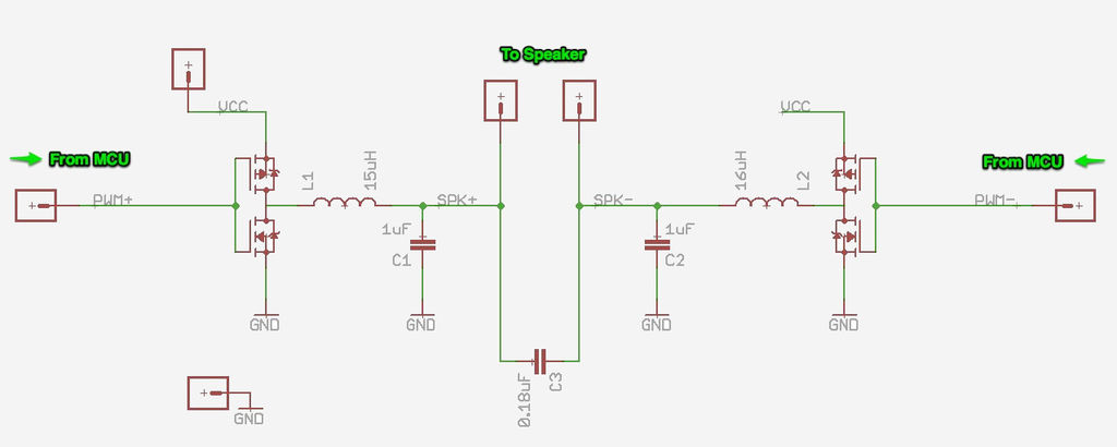
The audio amplifier is responsible for boosting the audio signal to a level suitable for driving speakers or headphones. It may utilize a Class D amplifier design for efficiency, which minimizes power loss and heat generation. This is particularly important in portable applications where battery life is a concern.
The DAC converts digital audio signals from a microcontroller or digital signal processor (DSP) into analog signals that can be amplified and output through speakers. The choice of DAC can significantly affect the audio quality, with higher-resolution DACs providing clearer and more detailed sound reproduction.
Additional components such as capacitors and resistors are utilized to filter the audio signal, eliminate noise, and manage power distribution. Proper layout and grounding techniques are essential to minimize interference and ensure a high-fidelity audio experience.
Overall, the circuit is engineered to deliver a seamless and engaging audio experience for users, enhancing the interactive capabilities of the Sifteo Base.Note: If you would like to learn more about the circuit that powers the Sifteo Base audio read on! Otherwise feel free to skip to the next step. Our.. 🔗 External reference
Related Circuits
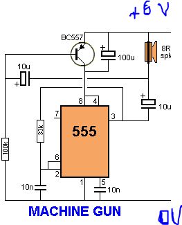
Understanding the pins of an integrated circuit (IC) is crucial for circuit construction. Pin 1 (GND) is connected to ground, representing a low voltage level (0 V). Pin 2 (TRIG) is used to trigger the operation of the circuit....
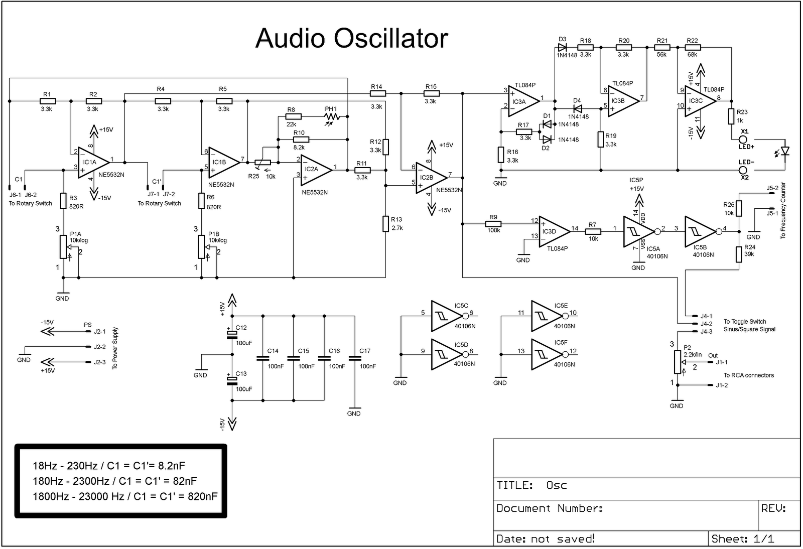
The project involves adding a DIY audio oscillator to a home workshop, which is essential for testing audio projects. While a basic oscillator is already available, it lacks a frequency counter. The design follows a schematic that provides a...
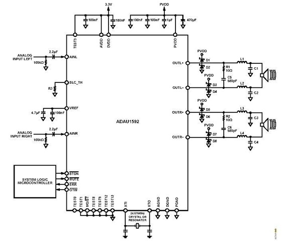
This is a stereo circuit schematic of the ADAU1592, a 2-channel, bridge-tied load (BTL) switching audio power amplifier. The ADAU1592 can be utilized in compact television sets, PC audio systems, and mini-component applications. According to the ADAU1592 datasheet, an...
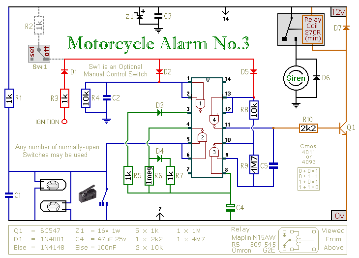
This circuit provides an intermittent siren output with an automatic reset feature. It can be operated manually through a key-switch or a hidden switch, and it can also be configured to activate automatically when the ignition is turned off....
The SSM2306 is a fully integrated, high-efficiency, Class-D stereo audio amplifier designed to maximize performance for portable applications. The application circuit requires minimal external components and operates from a single supply voltage ranging from 2.5 V to 5.0 V....
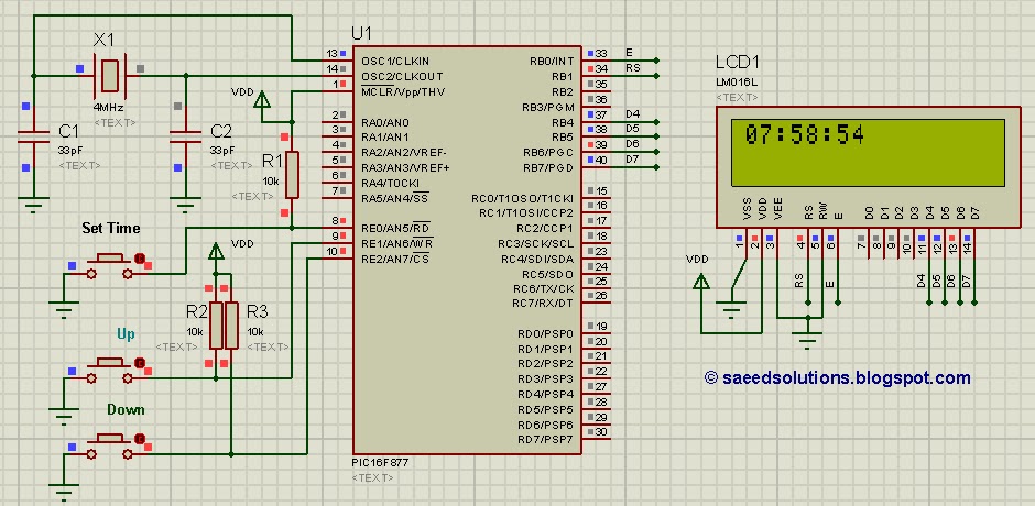
This tutorial on the PIC16F877 microcontroller addresses the question, "How to implement a controllable digital clock using the PIC16F877?" It utilizes the PIC16 simulator for demonstration purposes. The implementation of a controllable digital clock using the PIC16F877 microcontroller involves several...