
VCO circuit

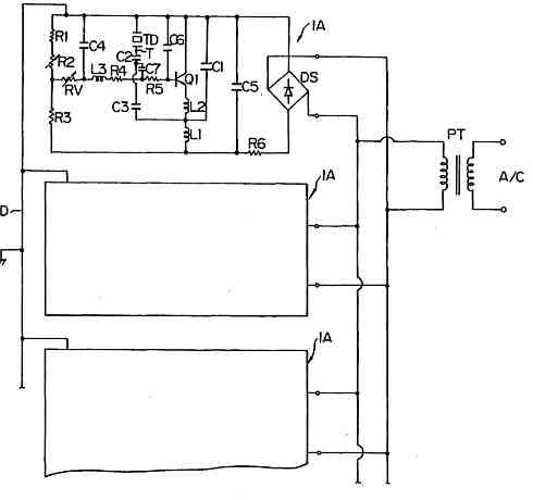
The theremin operates on the principle of heterodyning, where two oscillators generate signals that interact to create a difference frequency, producing audible sound. In the context of the Open Theremin, the selection of a stable oscillator is paramount to achieving consistent performance. The 4046 phase-locked loop chip is particularly advantageous due to its integrated voltage-controlled oscillator (VCO) capabilities, which allow for precise frequency adjustments and stability. The inclusion of a Z-Diode serves to ensure that variations in supply voltage do not adversely affect the oscillator's performance, thus maintaining the integrity of the sound output.
The choice of frequency is critical in the design of a theremin. The analysis of historical theremin designs reveals a range of operational frequencies, with Clara Rockmore's design exemplifying a lower frequency of 170kHz, while modern iterations like the Theremax push the boundaries up to 1MHz. However, it has been established that frequencies around 125kHz for RC circuits and 500kHz for LC circuits provide a balanced performance, facilitating both playability and sound quality.
Decoupling capacitors are essential in preventing cross-talk between oscillators when multiple units are used in proximity. This isolation ensures that each oscillator can function independently, preventing interference that could lead to unstable output signals. The unpredictability of circuit performance highlights the importance of empirical testing alongside theoretical calculations. Engineers and designers must be prepared to iterate on their designs based on real-world measurements rather than solely relying on simulations.
Finally, the sensitivity and response characteristics of the theremin are crucial for user interaction. A system that is overly sensitive may lead to a spongy feel, detracting from the musician's control and expressiveness. Understanding the exponential nature of musical scales is essential for designing a response curve that aligns with musical performance, ensuring that the theremin remains a versatile and expressive instrument.The basic principle of the theremin is theheterodyne oscillator. When I started developing the Open. Theremin I knew that I needed a stable and reliable oscillator. So I searched the internet and found various schematics with different components. I built them each on a small board and connected them to the micro controller to measure the performan ce. There are huge differences. Some did not work at all for me, others were not stable. For the variable oscillator I decided for the voltage controlled RC oscillator circuit inside the 4046 phase-locked loop chip. This integrated oscillator revealed to be much more stable than the other circuits I tested. Then there is also a Z-Diode in the package that can be used to stabilize the supply voltage. To adjust the resonated the R1 input can be used. Controlling by VcoIn did not provide better results. I also tested around with the optimum frequency and component values of the oscillators. Clara Rockmores theremin used a coil with 1165uH and 170kHz, theTheremax goes up to 1Mhz while most theremins are in the range of500-700kHz.
I did not find higher frequencies to be significantly better so I decided for 125kHz for the RC circuit and for 500kHz for the LC circuit. - Coupling of the resonators is a problem. It is almost impossible to put two oscillators in one circuit because the two oscillators try to pull one another to a common frequency and extinct the output signal.
One IC for each oscillator with proper decoupling condenser is best. - The performance of a circuit is hard to predict. Calculations do not always confirm what is common senses among theremin sites. Measurements do not alway confirm calculations. - Too low sensitivity and high range is not necessarily more comfortable to play. Playing gets spongy. Truly linear response is not desirable for audio applications since the music note system is exponential and not linear. 🔗 External reference
Related Circuits
GND and VCC are positioned perpendicularly to the other pins in the circuit diagrams, while the actual Z80 is a DIP with no pins in these locations. This arrangement complicates the readability of the circuit diagram, necessitating a mapping...
This quartz crystal oscillator circuit exhibits greater stability compared to a parallel resonance circuit. It is capable of generating frequencies up to 30 MHz or even higher when utilizing BFR91 transistors for T1 and T2, along with reduced values...
Ultrasonic atomizer circuit: How to generate an atomized water mist using ultrasonic sound waves. The ultrasonic atomizer circuit is designed to produce a fine mist of water by utilizing ultrasonic sound waves. This process involves the conversion of electrical energy...
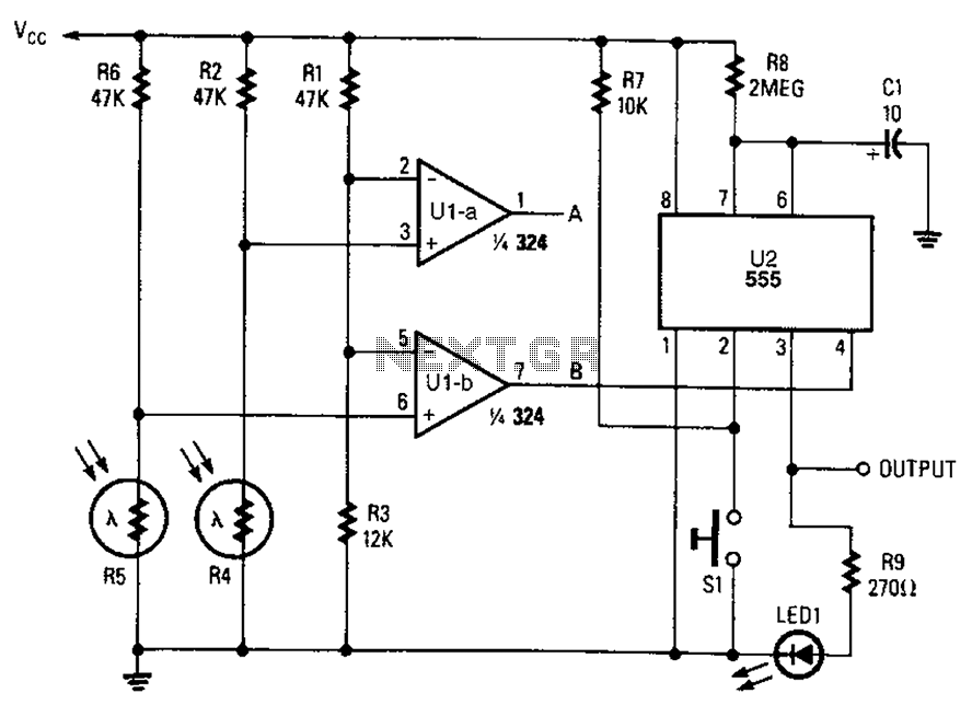
A combined monostable multivibrator using the 555 timer integrated circuit, along with a pair of light control comparators. This circuit can be utilized to control a load based on the timing parameters set within the circuit. The circuit comprises a...
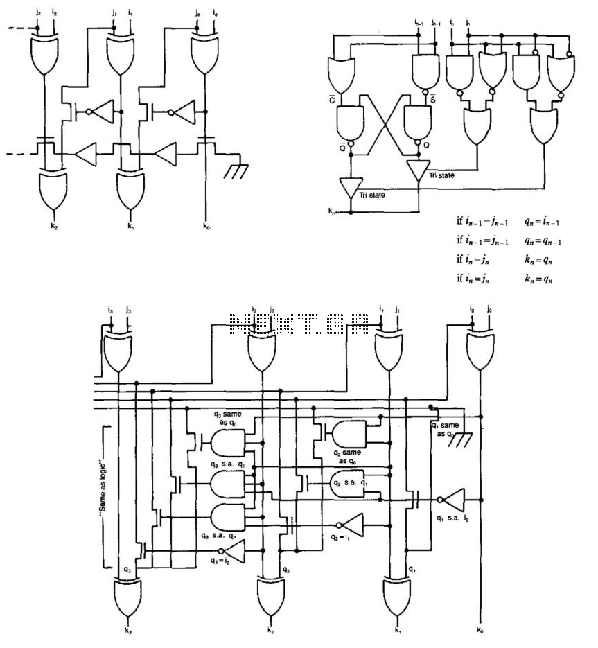
Some circuits that add binary numbers experience time delays due to carry propagation. This issue has been partially addressed by the carry look-ahead adder. However, the complexity of this method typically limits its application to no more than 4...
This is an upgraded circuit based on the Simple Volume Unit Display Circuit Diagram 1, featuring enhanced power for the audio input. Components include resistors. The upgraded circuit enhances the functionality of the original Simple Volume Unit Display by incorporating...