
An ultrasonic transmitter circuit diagram discrete components
The T/R-40-16 ultrasonic transmitter circuit is designed to generate ultrasonic waves at a frequency of 40 kHz, making it suitable for various applications such as distance measurement, object detection, and proximity sensing. The circuit operates with a supply voltage of 9V, which is a common voltage level for many electronic devices, ensuring compatibility with standard power sources.
The operating current of 25mA indicates a moderate power consumption, allowing for efficient energy use while maintaining performance. The circuit's capability to control distances up to 8 meters makes it versatile for use in different environments, such as industrial automation, robotics, and consumer electronics.
The circuit typically comprises several key components, including a signal generator, an ultrasonic transducer, and a power supply circuit. The signal generator produces the necessary 40 kHz waveform, which is then fed to the ultrasonic transducer. The transducer converts the electrical signal into ultrasonic sound waves, which propagate through the air.
In practical applications, the transmitter can be paired with a corresponding ultrasonic receiver circuit to measure the time taken for the ultrasonic waves to return after hitting an object, allowing for distance calculation based on the speed of sound. This feature is particularly useful in applications such as parking sensors, level measurement systems, and obstacle detection in autonomous vehicles.
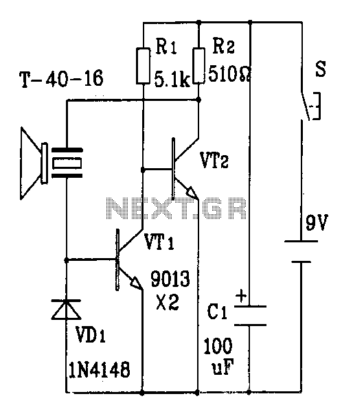
Overall, the T/R-40-16 ultrasonic transmitter circuit is a reliable and efficient solution for generating ultrasonic signals, with a well-defined operating range and power characteristics that make it suitable for various electronic projects and commercial applications.Discrete components ultrasonic transmitter circuit T/R-40-16 can emit a series of ultrasonic signal of 40kHz. This circuit voltage of 9V, operating current of 25mA, control dis tance of up to 8m.
Related Circuits

Construct a temperature controller circuit using the 555 integrated circuit (IC) in combination with a thermistor resistor divider. The benefit of this design is that it does not require a well-regulated power supply. The resistor divider network comprises an...
This project is used as an electronic private exchange. It has two telephones, which have the intercom facility, and they can be connected to the telephone line. All the functions are controlled by the 8-bit microcontroller AT89C2051 which has...
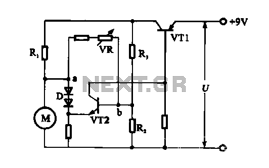
The electronic circuit for steady speed motor applications utilizes an automatic remote control system to regulate the motor power supply, thereby achieving consistent speed control. The circuit diagram illustrates a DC motor connected to the system. Given that the...
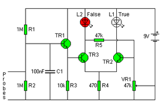
The following circuit illustrates a Lie Detector Circuit Diagram. Features include a capacitor that eliminates the 50Hz induced mains hum present in the circuit. The Lie Detector Circuit operates on the principle of measuring physiological responses, typically galvanic skin response...

Any number of normally-open switches may be utilized. Install "tilt" switches that close when the steering is moved or when the bike is lifted off its side-stand or pushed forward off its centre-stand. Employ micro-switches to secure removable panels...
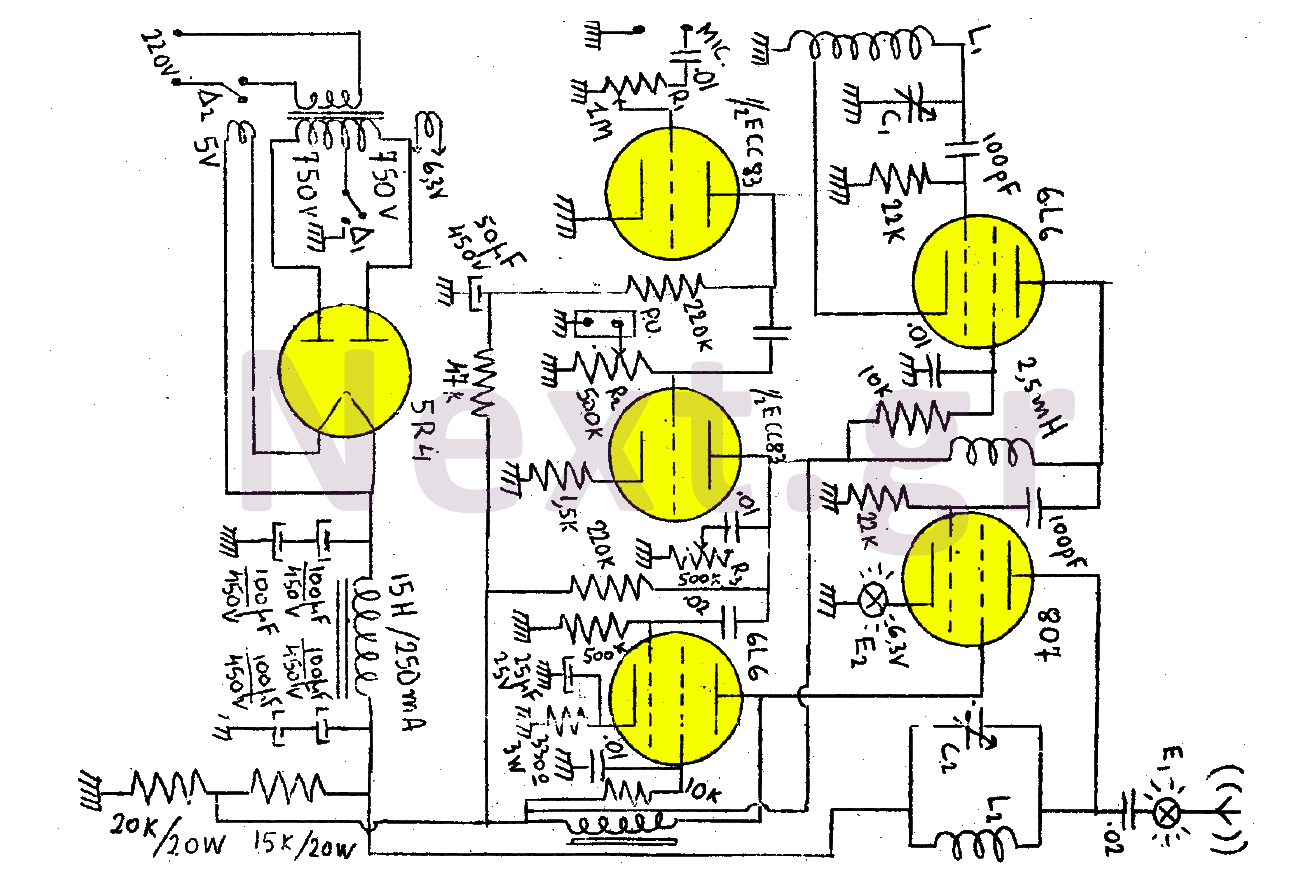
This transmitter consists of a total of five bulbs. The 6L6 tube functions as an oscillator, directing oscillations to the grid of the 807 tube, which serves as the final amplifier and the transmitter output lamp. The amplifier includes...