
Temperature Controller with 555 Circuit
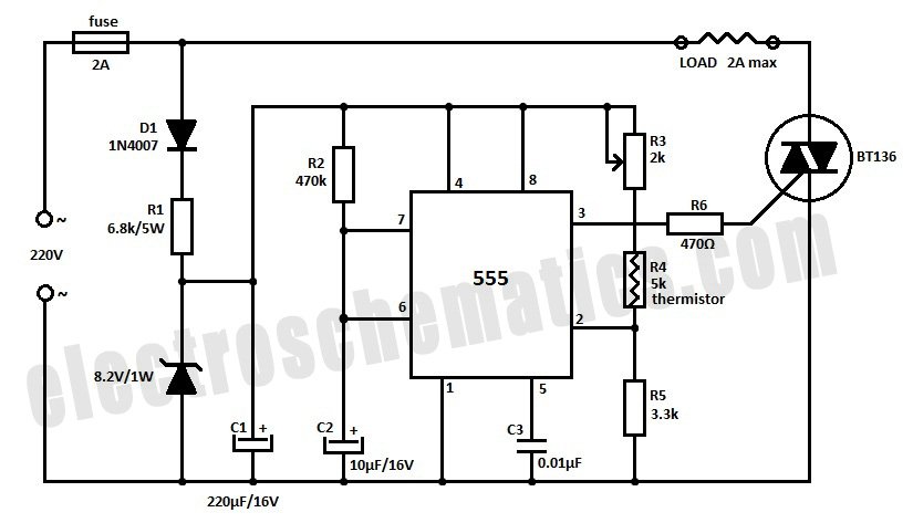
The temperature controller circuit leverages the 555 timer IC, which operates in monostable mode to regulate the heating element based on the temperature readings from the thermistor. The thermistor's resistance decreases with an increase in temperature, creating a voltage divider with resistors R3 and R5. The adjustable resistor R3 allows for fine-tuning of the temperature set point, providing flexibility in the system's operation.
In this configuration, the 555 timer's pin 2 serves as the trigger input, which responds to the voltage level determined by the thermistor and the resistors. When the thermistor detects a temperature below the set threshold, the voltage at pin 2 drops, triggering the 555 timer. The timer's output at pin 3 goes high, activating the triac that controls the power to the heater. This action initiates the heating process.
The timing cycle duration is determined by the external components connected to the 555 timer, typically involving resistors and capacitors that set the timing interval. If the thermistor detects a temperature rise above the set point during this timing period, the circuit is designed to cut power to the heater at the end of the timing cycle, preventing overheating. Conversely, if the temperature does not exceed the threshold, the heater remains energized until the timing cycle concludes.
This circuit design is particularly advantageous for applications where a stable power supply is not feasible, as it operates effectively with a wide range of input voltages. Overall, the 555-based temperature controller provides a simple yet effective solution for temperature regulation in various electronic and heating applications.Build a temperature controller circuit with the 555 IC together with a thermistor resistor divider. The advantage is that a well regulated power supply is not needed. The dividing network consists of adjustable resistor R3, thermistor R4 and R5. When the thermistor temperature is below a set value the voltage at pin 2 of the 555 drops belo w 1/3 of Vcc. This turns on the triac controlled heater and also starts the timing cycle. If the thermistor temperature rises above the set point before the end of the timing cycle the heater shuts off at the end of the timing period. Otherwise the heater continues to stay on. 🔗 External reference
Related Circuits
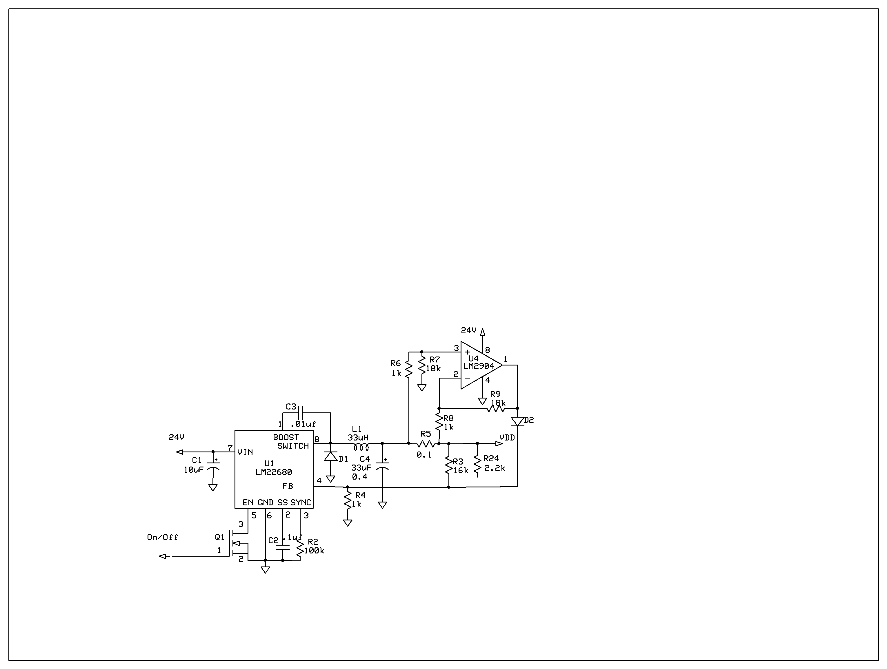
The product requires a voltage-controlled, current-limited power supply. Various switcher chips have been used with an op-amp to provide feedback for a current sense voltage to the feedback pin. Currently, an LM22680 is in use, but it has shown...
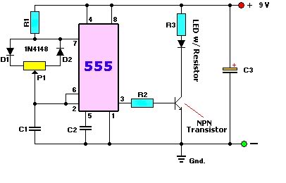
A user is new to the forum and has limited experience in DIY electronics. The current project involves creating a battery-powered LED dimmer circuit. The objective of the project is to design a battery-operated LED dimmer circuit that allows for...
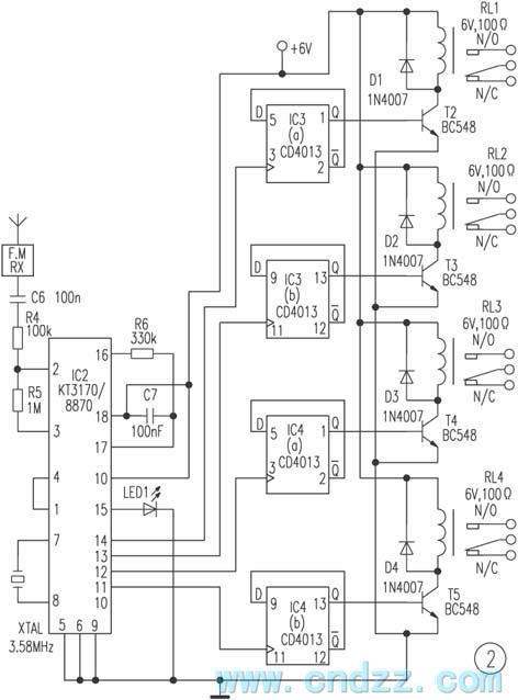
The remote control transmitter consists of a DTMF generator and an FM transmitter circuit. A UM91214B phone-specific integrated circuit (IC) is utilized to generate the DTMF signal, with a 3V power supply provided by a 3V zener diode (D1)....
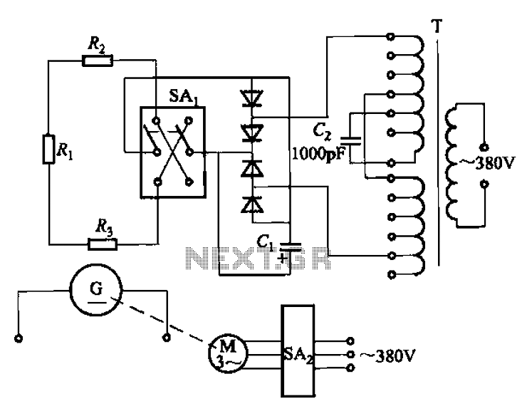
The AR-300 DC arc welding machine circuit includes the AX, AX1, AX3, and AR series. The structure of these machines is fundamentally similar, consisting of a three-integral unit converter, a phase asynchronous motor, and a DC arc welding generator...
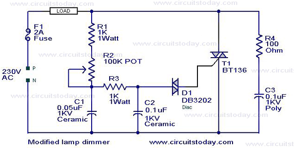
This is a modification of the Simple Lamp Dimmer/Fan Regulator circuit that was previously posted. The operation of the circuit remains the same as the original; however, it now includes a snubber circuit composed of resistor R4 and capacitor...
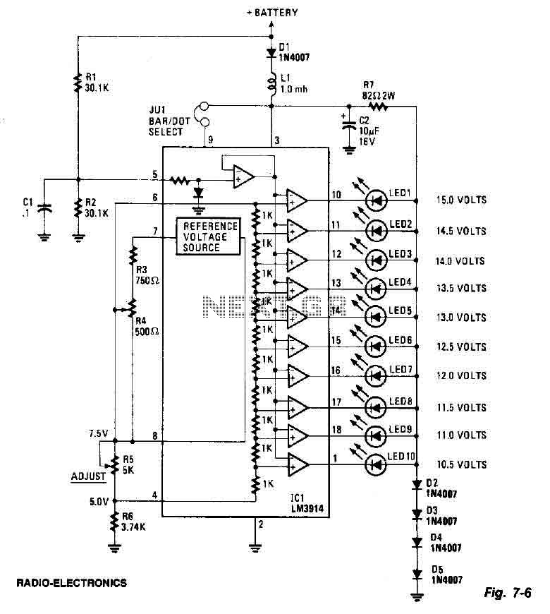
This screen utilizes ten LEDs to indicate a voltage range from 10.5 to 15 volts, with each LED corresponding to a 0.5-volt increment. The core component of the circuit is the LM3914 LED bar graph/display driver. A trimming potentiometer,...