
Electronic circuit steady speed motor application
The electronic circuit designed for steady speed motor applications functions by integrating an automatic remote control mechanism that regulates the power supply to the motor. This system is particularly beneficial for applications requiring consistent motor speeds, such as conveyor belts, fans, or automated machinery.
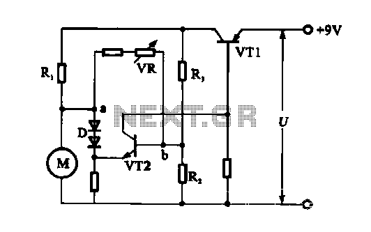
In the circuit, the DC motor is connected to a series of resistors (R1, R2, and R3) which are strategically chosen based on the impedance of the motor's coil winding. The relationship between the resistors is critical for achieving a state of equilibrium, ensuring stable operation. The motor generates a back EMF during its rotation, which counteracts the applied voltage. This back EMF is proportional to the speed of the motor; as the speed increases, so does the back EMF, thereby affecting the potential difference across points A and B in the circuit.
Transistor VT2 plays a pivotal role in controlling the motor speed. As the back EMF increases with higher motor speeds, the potential at point B rises, which causes the emitter voltage of VT2 to increase. This change results in a reduction of the base current flowing into VT2, leading to a decrease in the collector current. The collector current from VT2 is also linked to the base current of VT1, which further reduces VT1's collector current. This cascading effect ultimately results in a decrease in the voltage supplied to the motor, thereby reducing its speed in a controlled manner.
The design ensures that the motor operates within a predefined speed range, enhancing efficiency and prolonging the lifespan of the motor by preventing excessive speeds that could lead to mechanical failure. The circuit's automatic feedback mechanism allows for real-time adjustments, making it suitable for various applications where precision in motor speed is essential.Electronic circuit steady speed motor applications Electronic steady speed mode is automatic remote control over the role of the motor power supply circuit to the motor to achi eve steady speed control, shown is an application circuit. Figure (b), visible, DC motor connected to the circuit, as part of the circuit. Since the DC motor line has a coil winding impedance, then into the new circuit. So choose resistors RI, Rz, R3, so rIJRI R: Z/R3, state of equilibrium. Because during the rotation of the rotor coil generates counter electromotive force, and the role of the electromotive force of the motor causes the motor speed changes with the resistance rm, so between a, b will produce the motor speed is proportional to the potential difference. That is, when the motor speed increases, back electromotive force becomes large, a relative point b point potential becomes high.
VT2 of the transistor emitter voltage is raised, VT2 base current decreases, VI2 collector current also decreases. VT2 VT1 collector current is the base current of the transistor, which would also make the collector current decreases VT1.
Thus, for the motor power supply voltage drop, the motor speed is automatically reduced.
Related Circuits
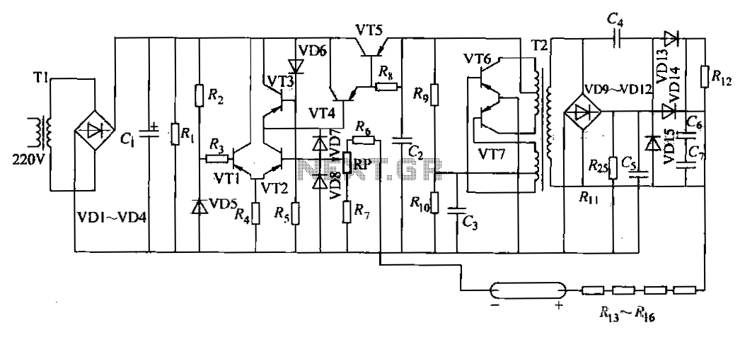
The DC power supply is a helium-neon laser excitation power supply, which is currently the most commonly used type of power supply. It is utilized in laser printers. The circuit includes a power transformer (T1), a high-voltage transformer (T2),...
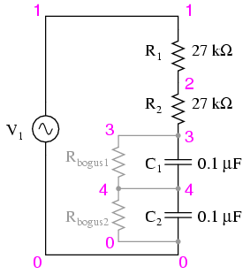
Construct the circuit and measure the voltage drops across each component using an AC voltmeter. Additionally, measure the total (supply) voltage with the same voltmeter. It will be observed that the individual voltage drops do not sum up to...
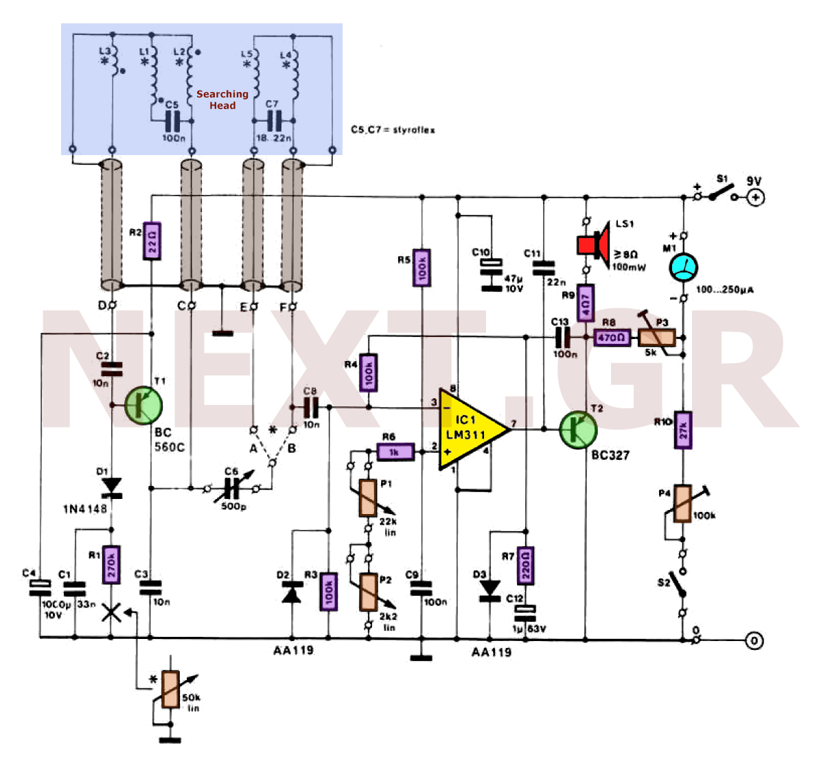
Metal detectors can be categorized based on their operational principles into three types: BFO (Beat Frequency Oscillator), TR/IB (Transmit-Induction/Balance), and PI (Pulsed Induction). Each method has its own set of advantages and disadvantages. An ideal metal detector, which does...
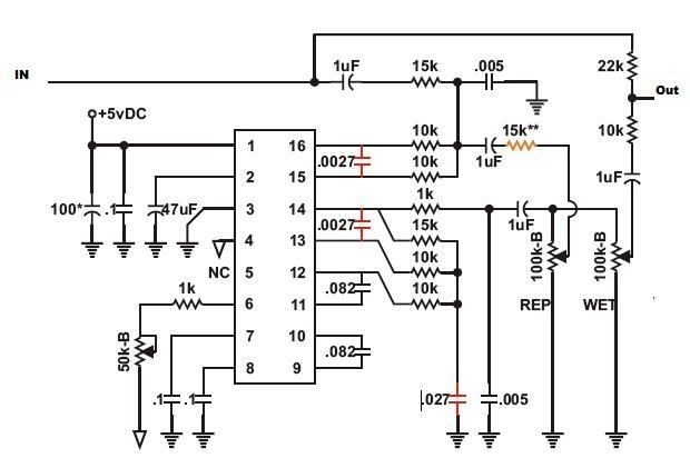
Recently, there has been a focus on Jeep repair due to an issue preventing the XJ from starting. However, during this time, progress has been made on initial modulation tests of the PT2399 circuit, resolving many bugs. The main...
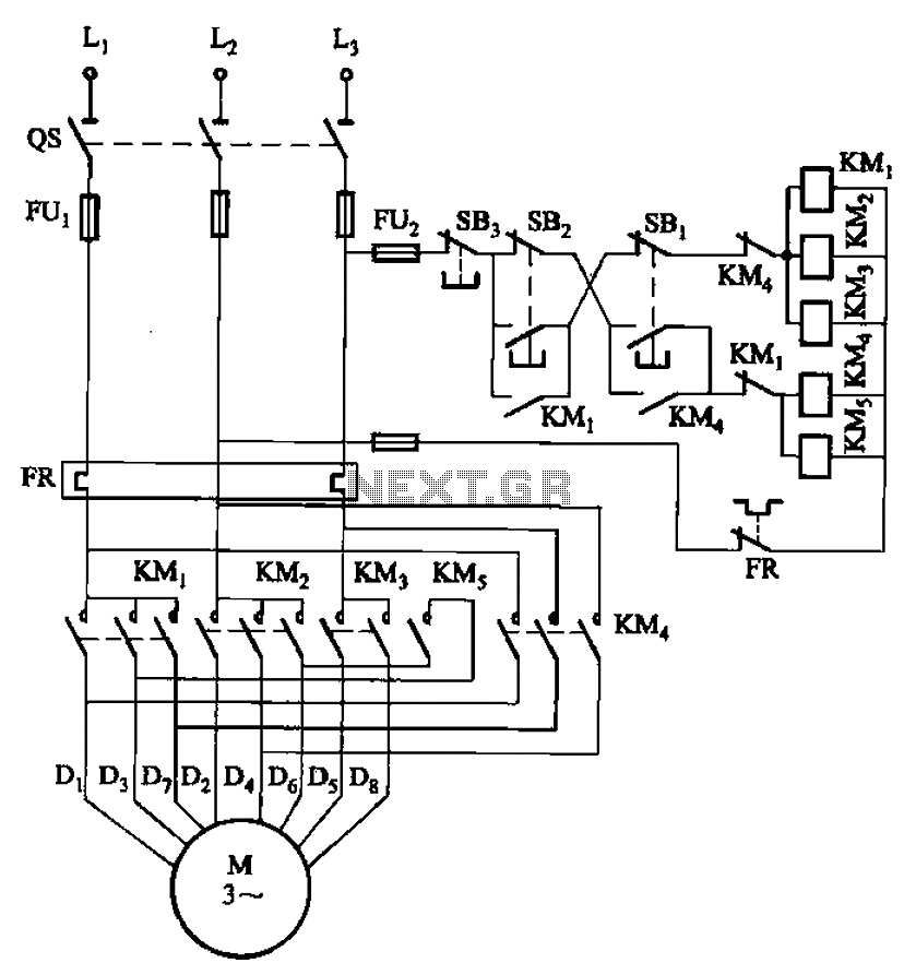
The circuit illustrated in Figure 3-104 features SB2, which functions as the low-speed operation button, and SBi, which serves as the high-speed operation button. The circuit design utilizes two distinct operational buttons, SB2 and SBi, to control the speed of...
This solid-state push-pull single-ended Class A circuit is capable of providing sound quality comparable to that of valve amplifiers. It delivers an output power of 6.9W when measured across an 8 Ohm loudspeaker cabinet load, with reduced total harmonic...
Warning: include(partials/cookie-banner.php): Failed to open stream: Permission denied in /var/www/html/nextgr/view-circuit.php on line 713
Warning: include(): Failed opening 'partials/cookie-banner.php' for inclusion (include_path='.:/usr/share/php') in /var/www/html/nextgr/view-circuit.php on line 713