
Analog Equaliser
The described circuit configurations are fundamental in audio signal processing, particularly in equalizers and filters. The time constants associated with R1C1 and R2C2 are critical in defining the bandwidth and frequency response of the filters. The Q-factor plays a significant role in determining the sharpness of the filter's response curve, with a value of 0.707 being a standard for achieving optimal performance without overshoot. The Butterworth response is particularly advantageous in audio applications due to its uniform gain across the passband, ensuring minimal distortion of the audio signal.
In practical applications, the low and high shelving equalizers allow for user-adjustable control over bass and treble frequencies, catering to personal preferences in audio playback. The use of potentiometers in the design facilitates a smooth transition in gain adjustments. The graphical equalizer expands on this concept by enabling multiple frequency bands to be adjusted independently, enhancing the versatility of the audio processing capabilities.
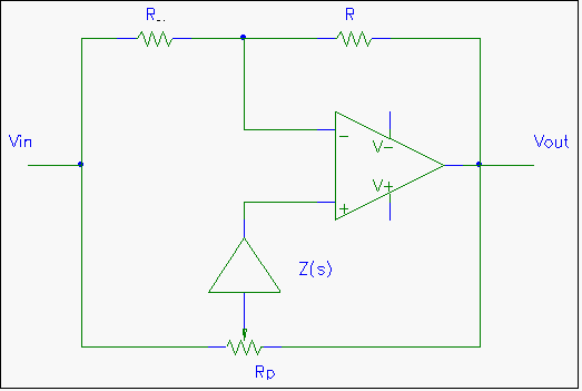
The implementation of various circuit topologies, including the use of gyrators, showcases the flexibility of the design approach, allowing for compact and efficient equalizer circuits. The emphasis on impedance characteristics is crucial, as it dictates the effectiveness of the equalization process, ensuring that desired frequencies are enhanced while minimizing interference from undesired noise. Overall, these circuit designs exemplify the intricate balance between theoretical principles and practical applications in audio technology.The time constant of R1C1 determines the low-cutoff frequency while the time constant of R2C2 determines the high cutoff frequency. The pass-band gain, Avpass=R2/R1. For a low-cut filter, that is a high-pass filter, Za must be capacitors and Zb resistors. By substituting Za=1/sC and Zb=R into above equation, the following equation is obtained: For a high-cut filter, that is a low-pass filter, Za must be resistors and Zb capacitors. By substituting Za=R and Zb=1/sC into above equation, the following equation is obtained: The best choice for the Q-factor is 0. 707. This results in the sharpest curve, without any overshoot. If this Q-factor is selected, the value of K must be 1. 586. Note that this is also the pass-band gain. The signal should therefore be attenuated if constant signal level is desired. If a slope steeper than 12db/oct is desired, a higher order filter can be used. It is best to use the Butterworth response for audio, because of its flat response. The simplest type of equaliser is the low and high shelving equalisers. This is usually called Bass and Treble on Hi-fi sets. Figure 3 shows the basic topology for such an equaliser. The potentiometer, Rp, sets the boost cut ratio. The impedance of Z(s) must be high at the frequencies to boost/cut and low at other frequencies, effectively shorting out Rp.
If a capacitor is substituted for Z(s), a low shelving equaliser is realised, while an inductor is needed for a high shelving equaliser. Figure 4 shows a circuit for a combined Lo and Hi shelving equaliser as used in conventional hi-fi sets and mixing consoles.
As can be seen, the inductor in parallel with Rtreble is omitted, C2 is instead inserted. At the high frequencies, Rbass is shorted out by C1. The higher the frequency becomes, the lower C2 s impedance become, giving the gain setting on Rtreble higher priority over the unity gain network formed by the lo section. The circuit in Figure 5 shows the basic circuit for a graphical equaliser. The frequency dependant impedance, Z(s), determines the centre frequency of the equaliser. The impedance of Z(s) must be low at the centre frequency, while high at other frequencies. By replacing Z(s) by a short it can be easily seen that the left part of Rp forms an attenuator feeding the input signal to the non-inverting operational amplifier, which gain is controlled by the right half of Rp.
If Z(s) is replaced by an open-circuit, Rp is only connected between the two input terminals of the op-amp, which is at the same potential and Rp does not effect the circuit. Multiple bands can be implemented by placing more than one pot in parallel, each with its wiper connected to a different Z(s) circuit.
It can be seen that if b<0. 5, that is Rp s wiper is moved toward the left, the gain is below unity, while if b>0. 5, that is Rp s wiper is moved toward the right, the gain is above unity. The maximum boost/cut ratio is controlled by the impedance of Z(s), which effectively limits the value of b so that a
To simplify the analysis of the circuit on the right, it is assumed that the impedance of C1, R1 is much higher than the impedance of C2, R2. A shelving equaliser can also be realised with this circuit topology. For a Lo shelving equaliser the circuit in Figure 6 can be replaced by a single capacitor in series with an resistor.
For a Hi shelving equaliser, the circuit in Figure 6 is used as it is, except that the high frequency roll-off of the impedance is above the audio spectrum. The same scheme can also be used for a Lo shelving equaliser. The advantage of this is that the circuits would not boost any unwanted noise beyond the audio spectrum.
Figure 7 shows a parametric equaliser circuit which is used in most older mixing c 🔗 External reference
Related Circuits
Free domains and hosting with up to 1GB of disk space, unlimited transfer, and access to PHP as well as 5 MySQL databases. The maximum size of a single file is not limited. This service offers a robust web hosting...
Before examining the various analog-to-digital (A-D) and digital-to-analog (D-A) conversion processes, it is useful to review the properties of each type of representation; in particular, this may help select the representation most suited to the problem at hand. An...
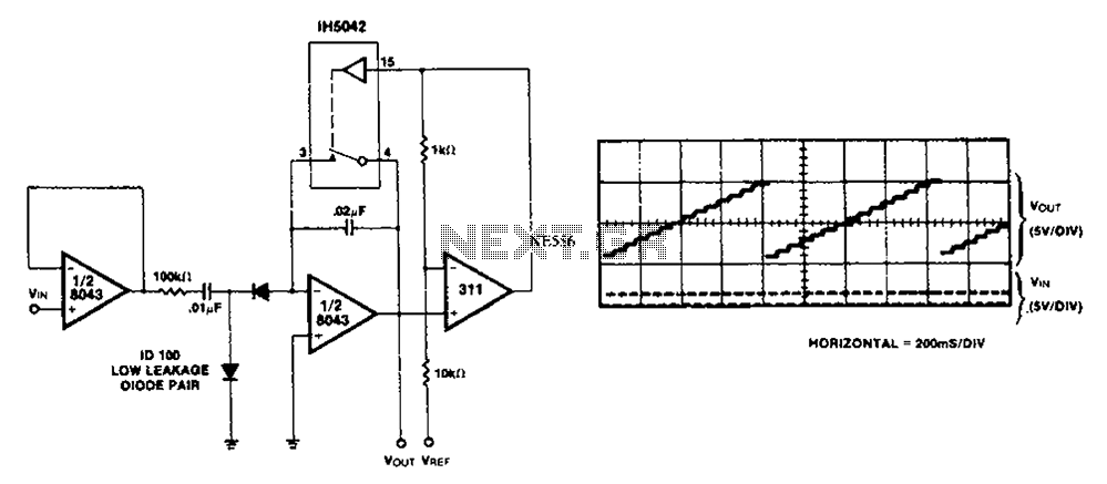
Low-frequency signals produced by transducers, measurement equipment, or data loggers often resemble the first waveform in the figure. The circuit operates as a tracking sample-and-hold, where transients are replaced in the output by the stored value of the current...
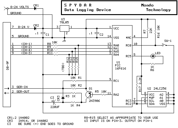
This is a circuit monitoring device. It runs for over 10 days and can log up to 32k events both digital and analog. Samples are logged either on a timing basis (0.01 to 2.5 seconds), or on a triggered...
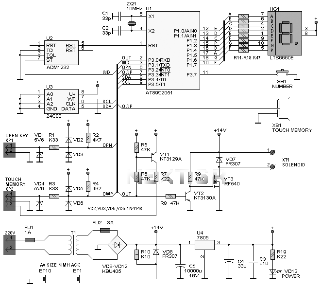
This simple circuit utilizes an LM311 as a level detector, incorporating CMOS analog switches to control capacitance. A significant feature of this counter is its ability to change numbers. The comparator operates more efficiently when there is a need...
The project involves implementing analog-to-digital conversion using the ADC0804LCN 8-bit A/D converter. A circuit will be designed and programmed so that when an analog signal is input, the corresponding digital voltage is displayed on an LCD. Essentially, the circuit...