
Analogue / Digital Logger II
pin-5 Ground
pin-7 8 to 24 Volts
pin-1 Input #1
pin-6 Input #2
pin-9 Input #3
pin-8 Input #4
(You will probably want to configure the unit for your specific use: see instructions below)
When power is applied to the unit with no computer connected, the LED flashes rapidly. This is the standby mode. Holding down the button for over 2 seconds causes the LED to go out. The unit is now armed and will react to changes in any of the 4 input lines (in the trigger mode), or just start storing (in the timing mode). After that, any event will cause a brief flash.
The data will be stored until one of the following occurs:
1. The 250 hour time limit is reached.
2. The 32k maximum events are stored.
3. The unit is powered off.
Once the data is captured, just disconnect it from the circuit you are testing. Then connect the unit to your computer running a terminal program and connect power to the units power connector. The device will sign on with something like...
Vers 2.1: Echo=OFF Dly=1 Trig=ON Ana=0
SPYDAR>
(Note: your serial cable must be connected before being powered up. The device uses the signal level to go into communications mode automatically)
This circuit monitoring device is designed for versatile data logging, capable of capturing both digital and analog signals over an extended period. With a logging capacity of up to 32,000 events, it is equipped to handle a variety of input configurations. Users can log data on a time-based schedule, with intervals adjustable from 0.01 to 2.5 seconds, or utilize a triggered logging mode that activates based on input changes.
The device incorporates four input channels, with the flexibility of utilizing up to three channels for analog data. Configuration and setup are performed via a terminal program, ensuring that users can tailor the device to meet specific monitoring needs prior to deployment. Once configured, the device operates independently, continuously monitoring the designated circuit.
Communication with the device is facilitated through a standard DB-9 connector, which serves dual purposes: data transfer during configuration and as a power interface. The device accepts a power supply ranging from 8 to 24 volts, with pin assignments clearly defined for ease of connection. It is essential to set the terminal program's baud rate to 19200, ensuring proper data transmission without parity, using full duplex settings.
In operational mode, the device enters a standby state indicated by a rapidly flashing LED until the user initiates data logging by pressing a button. This action transitions the device into an armed state, ready to log events based on the selected mode. Events are visually confirmed through a brief LED flash, providing immediate feedback to the user.
Data retention is governed by specific criteria, including a maximum logging duration of 250 hours, a cap of 32,000 events, or a power-down scenario. Post-logging, users can transfer data to a computer for analysis by reconnecting the device and powering it on. The initialization message confirms the device's readiness for data retrieval, indicating operational parameters such as echo status and logging modes.
This circuit monitoring device is an effective tool for engineers and technicians requiring reliable data logging capabilities in various applications. Its straightforward configuration and robust data handling features make it suitable for both experimental setups and long-term monitoring tasks.This is a circuit monitoring device. It runs for over 10 days and can log up to 32k events both digital and analog. Samples are logged either on a timing basis (.01 to 2.5 seconds), or on a triggered basis. Four inputs are provided, up to three of which can be analog. All setup and configuration is done via a terminal program. Once configured, the device can run stand-alone monitoring a circuit. The device can then be connected back to a terminal program for data retrieval. Any terminal program can be used to communicate with this device. Plug a standard DB-9 cable into the onboard connector and 8-24 volts into the power connector. Set the baud rate for 19200, full duplex, no parity, one stop bit and no hardware or software handshaking. (Note: only lines 2,3 and 5 are used for this function.) The same DB-9 connector is used in the stand-alone mode.
Simply make up a cable using a DB-9 male connector and any type of clips, connectors, or leads that you need. (Click on image above to see an example). In this mode, the connections are as follows: pin-5 Ground pin-7 8 to 24 Volts pin-1 Input #1 pin-6 Input #2 pin-9 Input #3 pin-8 Input #4 (You will probably want to configure the unit for your specific use: see instructions below) When power is applied to the unit with no computer connected, the LED flashes rapidly.
This is the standby mode. Holding down the button for over 2 seconds causes the LED to go out. The unit is now armed and will react to changes in any of the 4 input lines (in the trigger mode), or just start storing (in the timing mode). After that, any event will cause a brief flash. The data will be stored until one of the following occurs: 1. The 250 hour time limit is reached. 2. The 32k maximum events are stored. 3. The unit is powered off. Once the data is captured, just disconnect it from the circuit you are testing. Then connect the unit to your computer running a terminal program and connect power to the units power connector.
The device will sign on with something like... Vers 2.1: Echo=OFF Dly=1 Trig=ON Ana=0 SPYDAR> (Note: your serial cable must be connected before being powered up. The device uses the signal level to go into communications mode automatically) 🔗 External reference
Related Circuits
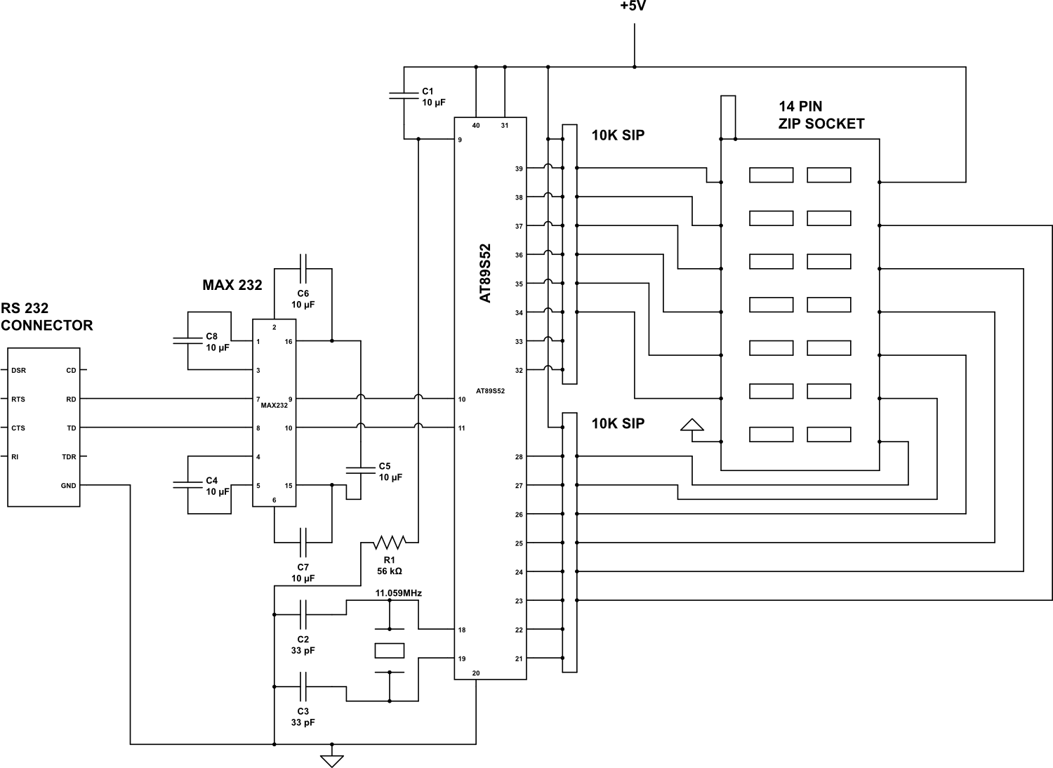
Check the following ICs: 7400, 7402, 7404, 7408, 7432, 7486. A Visual Basic program is utilized to display the results on the PC. The microcontroller AT89S52 receives the IC number from the PC, verifies the logic gates with the...

The 3130 CMOS operational amplifier provides the necessary high input impedance for a pH probe at a low cost. The output of the probe varies from a positive generated DC voltage for low pH values to 0 V for...
The M-8880 is a complete DTMF Transmitter/Receiver that features adjustable guard time, automatic tone burst mode, call progress mode, and a fully compatible 6500/6800 microprocessor interface. The receiver portion is based on the industry-standard M-8870 DTMF Receiver, while the...
This project utilizes the ISD2560P integrated circuit (IC), which enables the recording of 60 seconds of audio and subsequent playback with high fidelity. The schematic indicates that the input source is an electret microphone. If a dynamic microphone is...
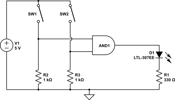
The AND output will be high when both switches are closed. However, there is no assurance regarding the input levels when the switches are open, resulting in unpredictable outcomes. In an electronic circuit utilizing an AND gate, the operation is...
This circuit measures the distance traveled during a walk. The hardware is housed in a small box that can be placed in a pants pocket. The display is designed as follows: the leftmost display D2 (the most significant digit)...
Warning: include(partials/cookie-banner.php): Failed to open stream: Permission denied in /var/www/html/nextgr/view-circuit.php on line 713
Warning: include(): Failed opening 'partials/cookie-banner.php' for inclusion (include_path='.:/usr/share/php') in /var/www/html/nextgr/view-circuit.php on line 713