
ANALOG FREQUENCY METER

The circuit employs a 555 timer configured in astable mode to generate a square wave output at a frequency proportional to the input frequency. The output pulse frequency from the 555 timer is fed into a counter circuit that counts the number of pulses within a specific time interval, typically one second. The counting mechanism is designed to provide a linear response, allowing the analog meter (M1) to display the frequency accurately.
For calibration, the meter can be adjusted using a variable resistor in parallel with the meter. This adjustment allows for precise scaling of the meter reading to match the input frequency range from 0 to 1 kHz. The circuit may also include filtering components to minimize noise and improve the accuracy of the frequency measurement.
In practical applications, the frequency meter can be used in various fields such as telecommunications, audio engineering, and signal processing, where measuring frequency is essential. The simplicity and effectiveness of the 555 timer in this configuration make it a popular choice for hobbyists and professionals alike in developing frequency measurement tools.This 1-kHz linear-scale analog frequency meter circuit uses the 555 as a pulse counter. Frequency is read on M1, (or 1 mA meter) which can be calibrated to read 0 to 1 kHz.. 🔗 External reference
Related Circuits
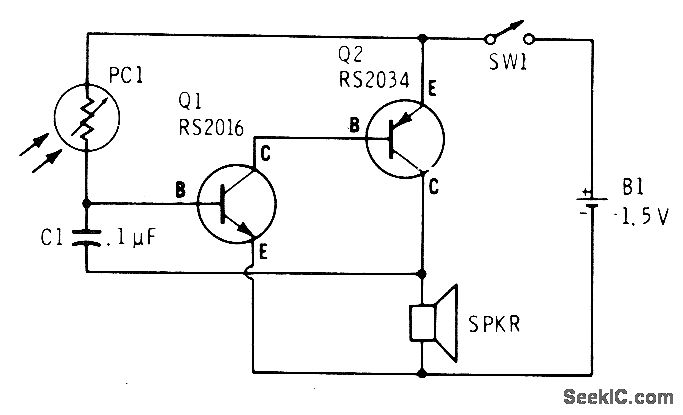
A low light condition on a cadmium sulfide photocell (Radio Shack 276-116) generates a series of clicks in a miniature 8-ohm loudspeaker. As the light intensity increases, these clicks coalesce into an audio tone that escalates in frequency with...
This tester is designed to locate stray electromagnetic (EM) fields. It can easily detect both audio and RF signals up to frequencies of around 100 kHz. However, this circuit is not a metal detector; it will detect metal wiring...
This project is a compact frequency counter capable of measuring frequencies from 1 Hz to 50 MHz, modified from the original design by Weeder Technologies. A new PCB has been designed to accommodate a 16x1 LCD, and the source...
This watt-meter circuit has a measurement range of up to 1 kW. It can provide complete (X)(Y) functionality while utilizing only one transistor. The circuit is designed for operation with 117 Vac ± 50 Vac. Modifications can be made...
This is a schematic diagram of a pulse width to analog demodulator circuit. This circuit is used to demodulate the pulse width to an analog voltage level. The pulse width to analog demodulator circuit is designed to convert pulse-width modulated...
S/PDIF is an acronym for Sony /Philips Digital Interface (or Sony /Philips Digital Interconnect Format). The full specification for the S/PDIF interface consists of hardware and software, but only the hardware side will be discussed here - the software...