
emf probe with meter
In a practical application, it was noted that a high-gain preamp built in the same enclosure as its power supply suffered from significant mains hum. This issue was not due to ripple on the power supply, which was regulated and well-smoothed, but rather because the audio circuit was constructed on a small piece of veroboard placed too close to the transformer, causing interference from the transformer’s own electromagnetic field. Modern solutions include the use of toroidal transformers, which have a significantly reduced hum field.
The circuit operates on the principle of electromagnetic field detection, leveraging an op-amp to amplify the incoming AC signals. The op-amp's gain and the characteristics of the probe's input capacitance are critical in determining the sensitivity and frequency response of the device. The inclusion of a 150 pF capacitor serves to limit the bandwidth and roll off gain at higher frequencies, ensuring that the circuit focuses primarily on the desired frequency range.
The probe design, incorporating a radial inductor and screened cable, is essential for minimizing interference and maximizing detection accuracy. The use of stereo headphones allows for real-time audio monitoring, providing immediate feedback on the presence of electromagnetic fields.
The full-wave rectification circuit, comprising diodes and a small DC panel meter, converts the amplified AC signal into a DC representation of the electromagnetic field strength, which can be easily read on the meter. The choice of a 250 µA meter ensures sufficient sensitivity for detecting low-level signals. This design can be further enhanced by incorporating additional filtering stages or adjustable gain settings, allowing for more precise measurements in varied environments.
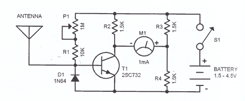
Overall, this tester serves as a valuable tool for identifying electromagnetic interference in electronic systems, enabling users to troubleshoot and mitigate issues related to stray EM fields effectively.This tester is designed to locate stray electromagnetic (EM) fields. It will easily detect both audio and RF signals up to frequencies of around 100kHz. Note, however that this circuit is NOT a metal detector, but will detectmetal wiring if it conducting ac current. Frequency response is from 50Hz to about 10kHz gain being rolled off by the 150p ca pacitor, the gain of the op-amp and input capacitance of the probe cable. Stereo headphones may be used to monitor audio frequencies at the socket, SK1. I used a radial type inductor with 50cm of screened cable threaded through a pen tube. The cable may be used with a plug and socket if desired. My probe is shown below: The output signal from the op-amp is an ac voltage at the frequency of the electro-magnetic field. This voltage is further amplified by the BC109C transistor, before being full wave rectified and fed to the meter circuit.
The meter is a small dc panel meter with a FSD of 250uA. Rectification takes place via the diodes, meter and capacitor. If you have access to an audio signal generator you can apply an audio signal to the windings of a small transformer. This will set up an electromagnetic field which will be easily detected by the probe. Without a signal generator, just place the probe near a power supply, mains wiring or other electrical device.
There will be a deflection on the meter and sound in the headphones if the frequency is below 15KHz. Switch on, plug in headphones (optional) and move the probe around. Any electrical equipment should produce a hum and indicate on the meter. I remember once building a high gain preamp (for audio use). I made a power supply in the same enclosure. The preamp worked, but suffered from an awful mains hum. This was not directly from ripple on the power supply as it was regulated and well smoothed. What I had done was built the audio circuit on a small piece of veroboard, and placed it within a distance that was less than the diameter of the transformer. The transformers ownelectromagnetic field was responsible for the induced noise and hum. I should however note, that this was when I was new to electronics with very little practical experience.
You can now buy toroidal transformers which have a much reduced hum field. 🔗 External reference
Related Circuits
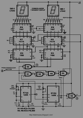
This circuit is designed to display the speed of a vehicle in kilometers per hour (km/h). An opaque disc is mounted on the spindle connected to the front wheel of the vehicle. The disc features evenly spaced holes along...
This circuit is a Logic Probe that indicates the logic state of any TTL logic circuit node. To operate, the probe must be supplied with the same power as the circuit being analyzed, including the same Vcc and GND....
SWR, or standing wave ratio, is the ratio of the amplitude of a partial standing wave at an antinode (maximum) to the amplitude at an adjacent node (minimum). SWR is a critical parameter in RF (radio frequency) engineering, particularly in...
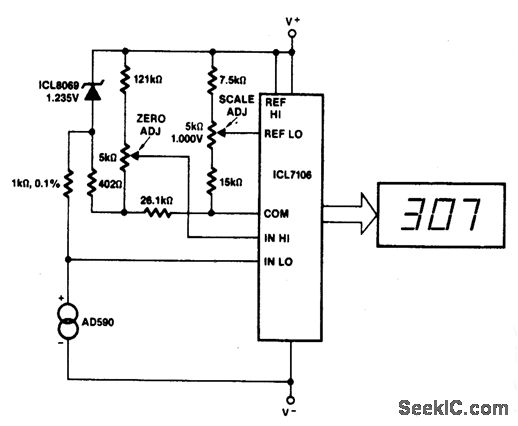
This circuit allows for zero adjustment as well as slope adjustment. The ICL8069 brings the input within the common-mode range, while the 5 K pots trim any offset at 218 °K (-55 °F) and set the scale factor. The...

This circuit utilizes a simple calculator along with a chip-on-board (COB) from an analog quartz clock to create a telephone call meter. The calculator converts STD/ISD calls into local call equivalents and continuously displays the current local call meter...
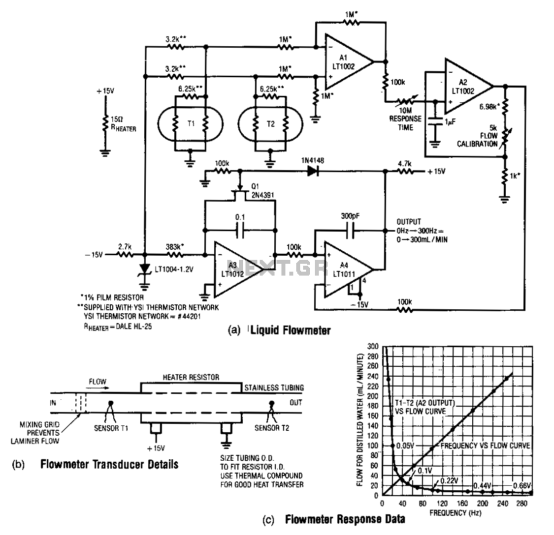
This design measures the differential temperature between two sensors. Sensor T1, located before the heater resistor, measures the fluid's temperature prior to heating by the resistor. Sensor T2 detects the temperature rise induced in the fluid by the resistor's...
Warning: include(partials/cookie-banner.php): Failed to open stream: Permission denied in /var/www/html/nextgr/view-circuit.php on line 713
Warning: include(): Failed opening 'partials/cookie-banner.php' for inclusion (include_path='.:/usr/share/php') in /var/www/html/nextgr/view-circuit.php on line 713