
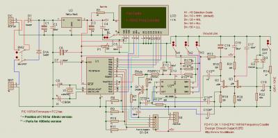
60MHz Frequency Meter / Counter 10Hz to 60MHz
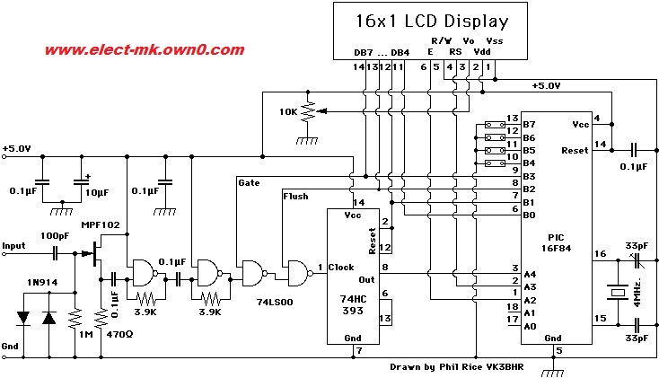
The frequency counter circuit is designed around a microcontroller that processes the incoming frequency signals and displays the results on a 16x1 LCD. The microcontroller is programmed to handle the auto-ranging feature, which allows the device to automatically adjust its measurement range based on the frequency detected. This is particularly useful for users who require precision across a broad spectrum of frequencies.
The PCB layout has been optimized for compactness, ensuring that the components are arranged efficiently to minimize signal interference and improve performance. The microcontroller interfaces with the LCD through a dedicated data bus, which transmits the frequency readings. The use of a floating decimal point in the display enhances readability, allowing users to quickly interpret the frequency measurements.
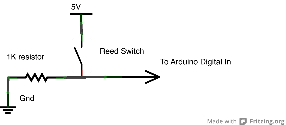
The input stage of the frequency counter includes a sensitivity circuit that can detect low-level signals, with an RMS sensitivity of 100 mV for frequencies up to 2 MHz. This sensitivity increases to 800 mV at the maximum frequency of 50 MHz, ensuring accurate readings across the entire operational range. Additionally, the input overload protection circuit safeguards the device against excessive input signals, preventing damage to the microcontroller and other sensitive components.
The detachable LCD feature, facilitated by the 16-pin headers, allows for easy assembly and maintenance. The male header is soldered to the LCD, while the female header is soldered to the PCB, providing a secure yet removable connection. This design choice not only simplifies repairs but also allows users to replace the LCD if necessary without extensive modifications to the circuit.
Overall, this frequency counter project combines advanced features with user-friendly design, making it an effective tool for a variety of applications in electronics testing and measurement.This project is nice and small frequency counter that reads frequency from 1 Hz to 50 MHz that I have modified from original designed by Weeder Technologies . I have designed new PCB to fit with 16X1 LCD and change source code for compatible with new small PCB Specifications - Auto-ranging with floating decimal point.
- Up to 7 digits displayed on 1X16 LCD. - Auto-adjusting gate speed (0.1 sec to 1 sec). - Microcontroller-based circuitry provides for simplicity, ease of assembly, and highly stable readout. - Sensitivity approximately 100 mV RMS (100 Hz to 2 MHz), 800 mV RMS @ 50 MHz. - Input overload protected. LCD display is connected to PCB by 16-PIN male & female header and is easily detachable from the main board. 16-PIN Male Header must be soldered to LCD display. 16-PIN Female Header must be soldered to PCB. 🔗 External reference
Related Circuits
The Power Node has been utilized to monitor home power usage. An additional project involves monitoring water usage. The main water meter is a positive displacement disk meter, consisting of a collection unit and a counter unit. Water flows...
One of the goals of Movable Party is to provide an interactive experience for audiences and participants. Power will be generated from a hub motor attached to the rear wheel of each bike, with the speed of the rear...
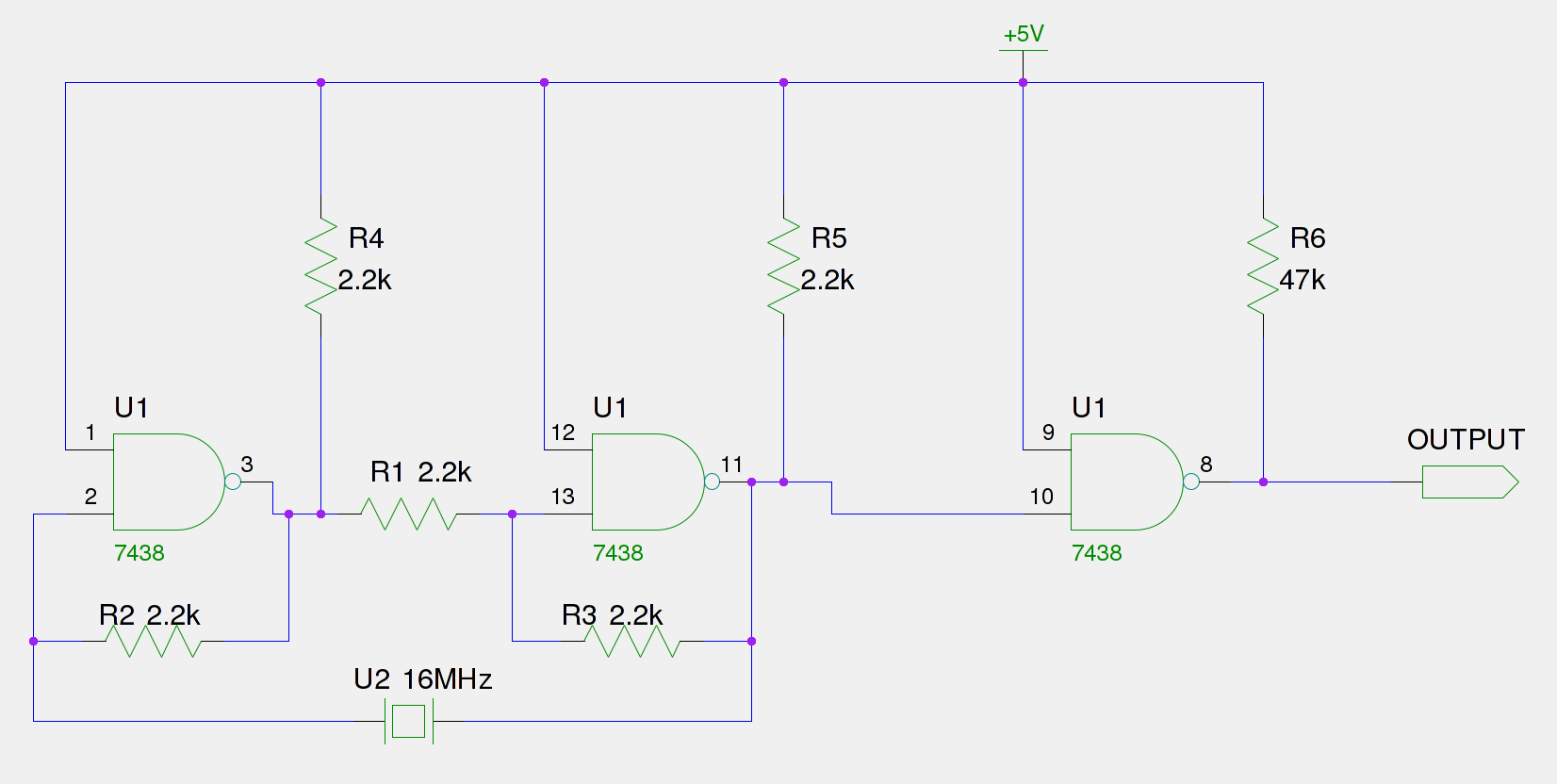
An old Eistar SJ-1 digital pulser has been acquired. However, the frequency it generates is consistently 66% of the expected output. The frequency observed at the frequency stage (Pin 11) is 66% of the 16 MHz crystal, which equates...
The following circuit illustrates a 40 MHz/400 MHz Frequency Counter Circuit Diagram. This circuit is based on the PIC16F84 IC. Features: The frequency counter circuit operates within the range of 40 MHz to 400 MHz, utilizing the PIC16F84 microcontroller...
Frequency meter circuit for service applications, including all standard frequency bands: amateur HF, VHF, and UHF, displayed on an LCD screen. The frequency meter circuit is designed to accurately measure and display frequency across various amateur radio bands, specifically HF...
While it may lack the aesthetic appeal of traditional mercury barometers featuring elongated glass tubes mounted on intricately carved wood, the Torricelli barometer presented here serves as a functional equivalent and an electronic representation of the original Torricelli barometer....