
Analog Timing Light Project
The described timing light circuit employs a resistor-capacitor (RC) network to create a time delay that governs the operation of an incandescent lamp. The fundamental operation relies on charging and discharging the capacitor through the resistor, which determines the time interval before the relay deactivates the lamp.
In this circuit, the capacitor is charged through the resistor when power is supplied. The time constant, defined as the product of the resistance (R) and capacitance (C) values (τ = R × C), dictates how long the capacitor takes to charge to a specific voltage level. Once the voltage across the capacitor reaches a predetermined threshold, typically set by the relay's control voltage, the relay is activated, allowing current to flow to the incandescent lamp.
The relay acts as an electronic switch, enabling the control of higher power loads without the need for a direct switch. When the capacitor discharges after reaching the threshold, the relay is deactivated, turning off the lamp. This mechanism ensures that the lamp remains lit for a specified duration after the triggering event, providing functionality for applications such as automotive timing lights or decorative lighting systems.
Additional components may include a diode across the relay coil to prevent back EMF from damaging other circuit elements, as well as a potentiometer to allow for adjustable timing settings. Proper selection of the resistor and capacitor values is essential to achieve the desired delay time, making this circuit versatile for various timing applications.
Overall, this simple yet effective timing light circuit demonstrates the practical use of RC timing principles in controlling incandescent lamps through relay actuation.This simple electronics timing light uses RC circuit as a delay OFF timer to control an incandescent lamp by using a relay 🔗 External reference
Related Circuits
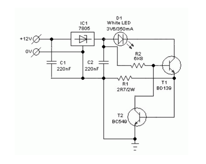
A simple and safe white LED driver circuit has been designed for use in 12V automobiles, allowing for the efficient operation of standard high-efficiency white LED modules powered by automotive battery systems. The circuit utilizes a fixed voltage regulator...
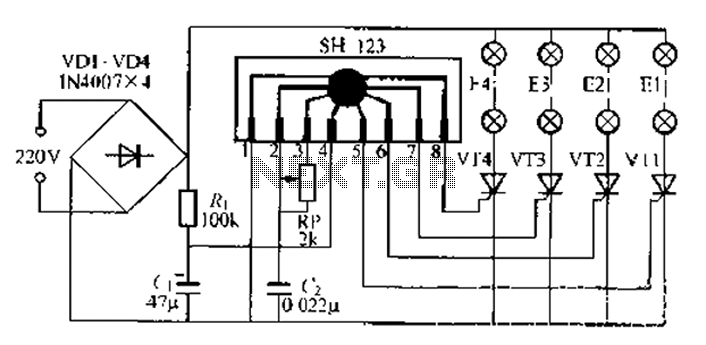
A water Happy Valley-type four flashing lights string controller, electric bollard is designed for use with a type J Ding Japanese lantern. The circuit employs a specific integrated circuit (IC) utilizing CMOS technology. It features a black soft cream...
The simulation of behavioral DSP designs alongside analog/RF circuit designs is essential for the successful integration of components, devices, and subsystems in modern wireless applications. Verifying the effects of real-world analog/RF issues on DSP algorithms, and vice versa, within...

The HC-06 module is a slave mode serial Bluetooth data link manufactured by CSR. In this project, a mobile phone communicates with the AT89C2051 microcontroller via the HC-06 module. The complexity of the communication has been encapsulated within a...

In 1991, there was significant interest in a specific display technology that was difficult to find locally and expensive to import. Currently, this technology has become widely available and is considered obsolete due to the affordability and accessibility of...
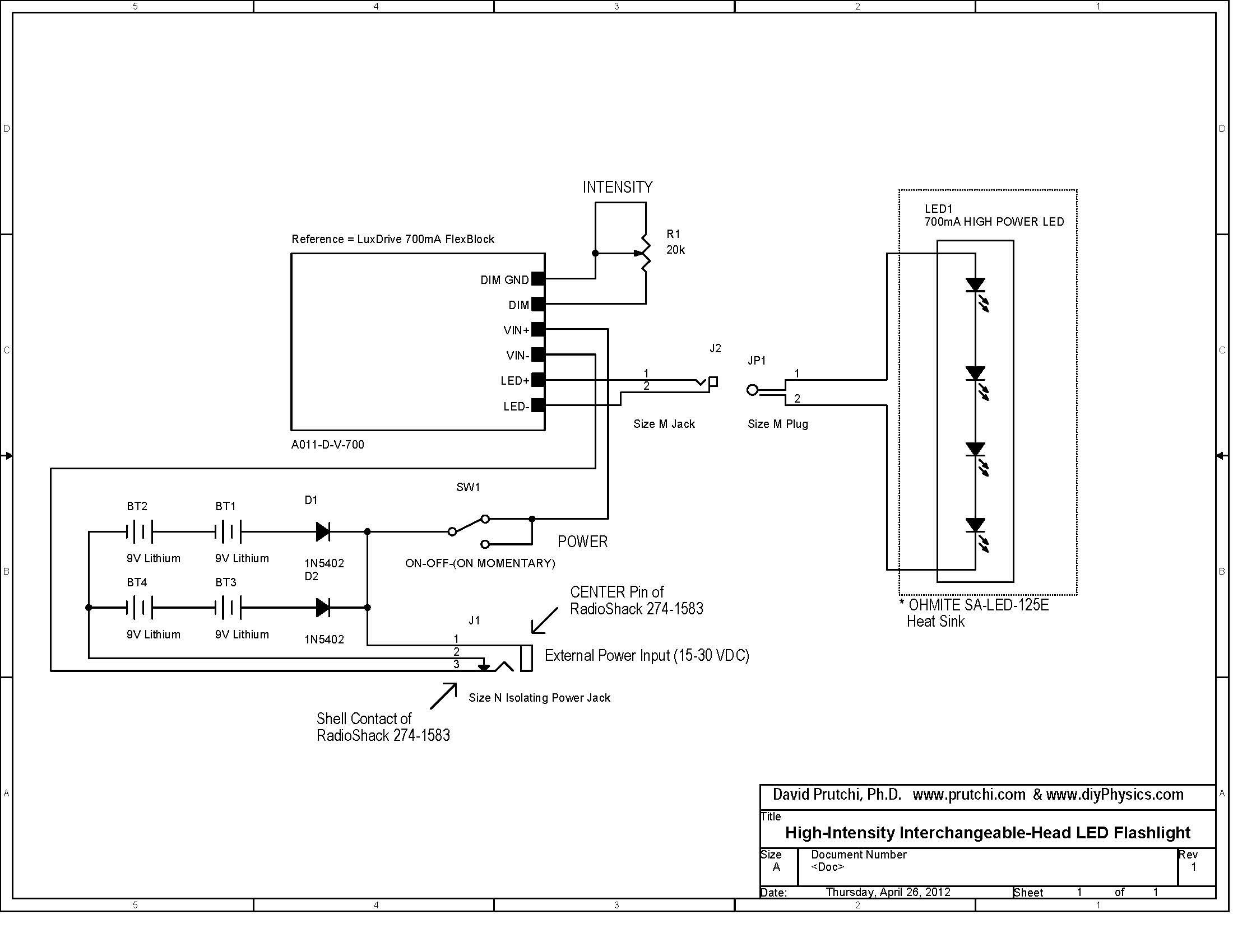
Build a 10W LED flashlight that features swappable UV, IR, and visible light heads. This flashlight is designed to complement a photographer's toolkit for applications such as light painting, infrared illumination, UV-reflected photography, or UV fluorescence photography. The flashlight...