
analysis and design of a quadrature oscillator

The analysis of oscillators operating in quadrature focuses on the generation of two signal outputs that are 90 degrees out of phase with each other. This type of oscillator is essential in various applications, including phase-locked loops (PLLs), communication systems, and RF applications, where precise phase relationships are necessary.
The typical architecture of a quadrature oscillator includes a core oscillator circuit, often based on a feedback loop that can utilize components such as transistors, capacitors, and inductors. The feedback network is designed to ensure that the output signals are in quadrature, which can be achieved through the use of phase-shifting networks or by employing differential pairs of active devices.
In the HSPICE simulation, the oscillator circuit can be modeled using standard components. The design may include a differential amplifier configuration to produce the quadrature outputs. The analysis in HSPICE will involve setting up the circuit parameters, including biasing conditions, and simulating the frequency response and stability of the oscillator. Key performance metrics such as phase noise, output power, and frequency stability can be extracted from the simulation results.
To ensure accurate operation, the design should also consider the effects of parasitic capacitances and inductances, which can influence the oscillator's performance. Careful selection of components and layout design is critical in high-frequency applications to minimize unwanted coupling and interference.
Overall, the design and analysis of quadrature oscillators are vital for achieving high-performance signal generation in modern electronic systems.This post details the analysis and design of two oscillators operating in quadrature. I will first give a brief explanation on how the circuit works, and then present a design in HSPICE of the operation of the circuit. This post is taken directly from the oscillators chapter of RF Microelectronics by Behzad Razavi. A more.. 🔗 External reference
Related Circuits
This article discusses practical techniques for incorporating "correctness by design" in DDR2 interfaces from a Signal Integrity (SI) perspective, utilizing the current generation of available design tools. It analyzes common DDR2 design errors and the trade-offs between various popular...
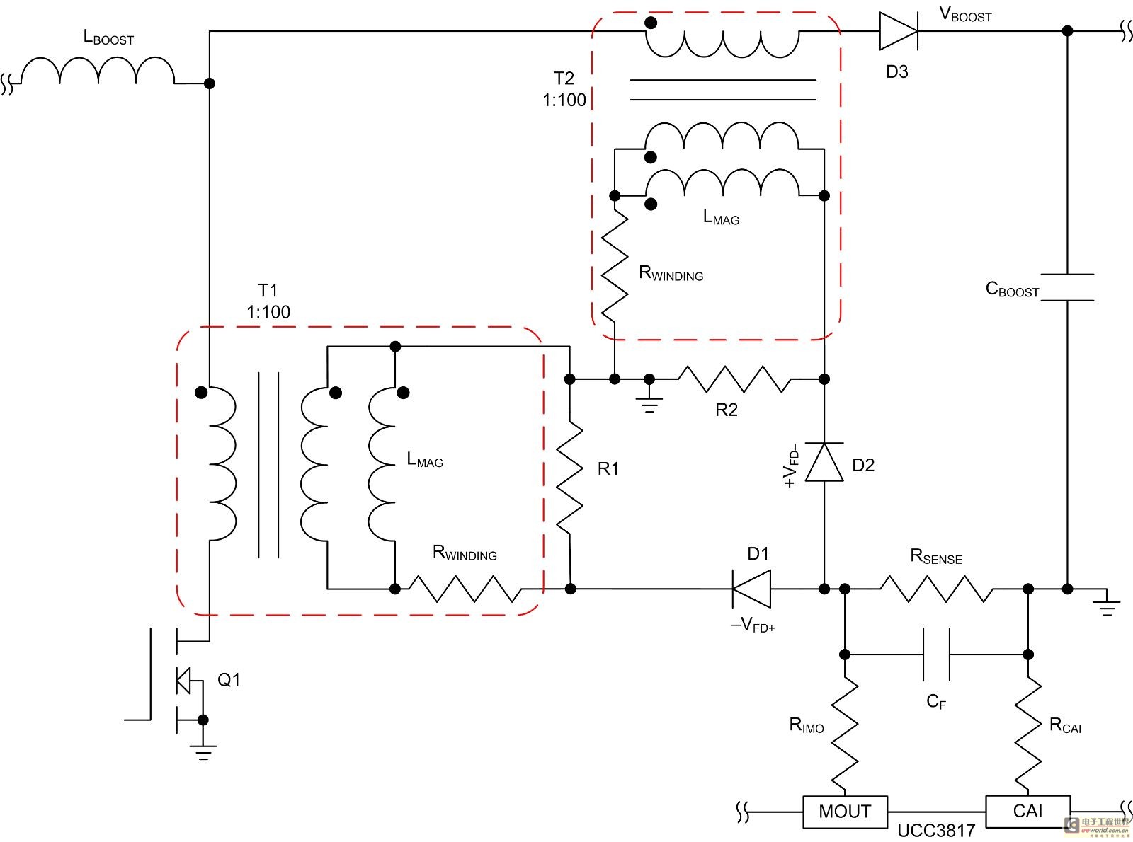
Mode control of the average current (CMC) is necessary to regulate the overall waveform of electric current during the rebuilding cycle. This text recommends selecting specific parameters related to the voltage transformer and outlines steps for designing a circuit...
A Programmable Logic Device (PLD) will be utilized to control seven-segment displays. The design will incorporate 8 outputs from an Analog to Digital Converter (ADC) as inputs to the PLD, which will generate 14 outputs to drive the segments...
There are various configurations for crystal oscillators, with the most common being discrete and integrated circuits like the Pierce and RLC Bridge. The discrete Pierce oscillator is a suitable choice when good frequency stability and a relatively simple circuit...

Phase-shift oscillator. An oscillator in which a network has a phase shift of 180 degrees. A phase-shift oscillator is a type of electronic oscillator that generates a sinusoidal output signal. It typically consists of an amplifier and a phase-shifting network...
Battery-powered devices, such as electric toothbrushes, shavers, cell phones, PDAs, MP3 players, and remote controls, are integral to daily life. Consequently, power management has become a critical consideration for embedded designers. Microcontrollers (MCUs) provide various methods for managing power...