
Analysis of a Digitally Controlled Wien-Bridge Oscillator
The Wien-bridge oscillator is a type of electronic oscillator that generates sine waves. It utilizes a bridge circuit that consists of resistors and capacitors to establish the necessary phase shift for oscillation. The fundamental operational principle of the Wien-bridge oscillator is based on the balance of impedances in the bridge circuit, which allows for the generation of a stable frequency output.
A key component of the Wien-bridge oscillator is the use of a JFET (Junction Field-Effect Transistor), which acts as a gain element. The JFET is essential for maintaining oscillation by providing the necessary gain to overcome losses in the circuit. Its high input impedance and low noise characteristics make it an ideal choice for this application. The gain of the JFET can be controlled dynamically, allowing for automatic adjustment of the oscillation amplitude.
Incorporating a digital potentiometer (digipot) instead of a traditional variable resistor offers several advantages. The digipot allows for precise control over resistance values through digital signals, which enhances the stability of the oscillator. This digital control enables fine-tuning of the oscillation frequency and amplitude without the mechanical wear and variability associated with analog potentiometers. Additionally, the integration of a microcontroller can facilitate automated adjustments based on real-time feedback, further improving the performance and reliability of the oscillator circuit.
Overall, the combination of a Wien-bridge oscillator with a JFET and a digital potentiometer represents a modern approach to generating stable sine wave signals suitable for various applications, including signal processing, waveform generation, and audio applications. The flexibility and precision offered by this configuration make it a valuable tool in the field of electronics.This application note analyzes the details of a Wien-bridge oscillator, shows how a JFET maintains oscillation, and demonstrates adding a digital potentiometer (digipot), rather than a variable resistor, to improve stability and flexibility.. 🔗 External reference
Related Circuits
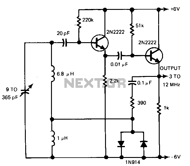
The gain control enables the oscillator to maintain a nearly constant output across its range. The circuit operates within a frequency range of 160 kHz to 12 MHz while producing a consistent amplitude. The oscillator circuit described utilizes a gain...
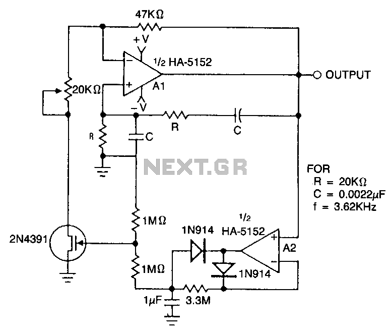
This circuit employs an HA-5152 dual operational amplifier and a field-effect transistor (FET) to create a low-voltage, low-power Wien bridge sine-wave oscillator. The frequency of oscillation is controlled by resistors and capacitors, while the FET functions as a voltage-controlled...
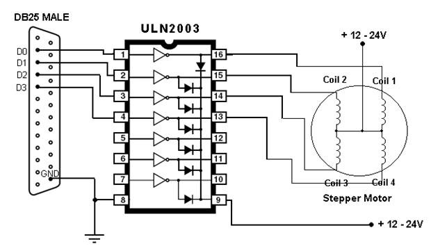
This article outlines the process of connecting a stepper motor to a computer's parallel port and writing code to control it using the scroll wheel of a mouse. For those unfamiliar with stepper motors, this project offers an engaging...
The Pierce-gate oscillator of Figure 1 is well recognized by most designers, but few understand how to specify the crystal correctly. The crystal used in the topology of Figure 1 can be either a fundamental AT-CUT or BT-CUT. A...
The schematic illustrates the division of a crystal oscillator signal by the crystal frequency to achieve a precise 1-second time base with an accuracy of 0.01%. Two cascaded 12-stage counters (CD4040) create a 24-stage binary counter, with specific bits...
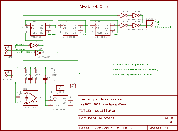
The oscillator generates a 1 MHz and a 1 kHz clock signal. The 1 MHz clock serves as the primary clock for the microcontroller and provides a time base for millisecond measurements. A 2 MHz signal is divided by...