
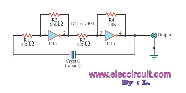
Pierce-gate oscillator
The Pierce-gate oscillator is a popular circuit configuration used in various applications, particularly in frequency generation and timing circuits. The core of this oscillator is the use of a crystal, which serves as a frequency-determining element. The choice between an AT-CUT and a BT-CUT crystal is critical, as it impacts the oscillator's performance. AT-CUT crystals are preferred for applications requiring high frequency stability across a range of temperatures due to their superior temperature coefficient characteristics. In contrast, BT-CUT crystals are less stable and may introduce frequency drift, making them less suitable for precision applications.
In the specified topology, the oscillator utilizes a parallel resonant crystal configuration rather than a series configuration. This distinction is essential because the parallel configuration allows the circuit to achieve a higher quality factor (Q), resulting in a sharper resonance peak and improved frequency stability. The load capacitance specified by the manufacturer is a critical parameter that must be accurately defined to ensure that the oscillator operates at the desired frequency. This load capacitance, denoted as CL, interacts with the crystal's inherent capacitance (C0) to determine the overall resonant frequency of the oscillator.
Understanding the relationship between the load capacitance and the crystal's inductance is vital. The crystal can be modeled as an inductor (L) in series with a load capacitance (C), forming an LC circuit. The resonant frequency (f0) of this circuit can be expressed by the formula:
f0 = 1 / (2π√(LC))
In this case, the inductance (L) remains constant, as it is determined by the physical properties of the crystal, while the load capacitance (C) can be adjusted to achieve the desired operating frequency. Proper specification of the load capacitance is crucial, as it directly influences the oscillator's performance, including stability, frequency accuracy, and phase noise characteristics.
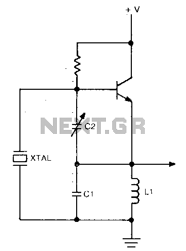
In summary, the Pierce-gate oscillator is a versatile circuit that requires careful consideration of crystal selection and load capacitance specification to optimize performance for specific applications. Understanding the nuances of AT-CUT versus BT-CUT crystals and the implications of load capacitance is essential for designers seeking to implement reliable and accurate frequency generation solutions.The Pierce-gate oscillator of Figure 1 is well recognized by most designers, but few understand how to specify the crystal correctly. The crystal used in the topology of Figure 1 can be either a fundamental AT-CUT or BT-CUT. A BT-CUT crystal has poor frequency stability over temperature compared to an AT-CUT. This topology uses a parallel crystal and not a series crystal. When a parallel crystal is specified, the crystal manufacturer will also require that you specify a load capacitance.
To understand load capacitance, think of a series LC circuit where the crystal is the L and the load capacitance is the C. The resonance frequency of the LC circuit will vary as a function of L and C. But in the crystal case, the L is fixed (temperatur
🔗 External referenceRelated Circuits
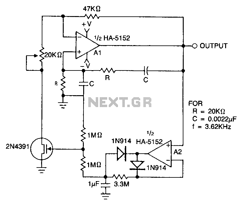
This circuit employs an HA-5152 dual operational amplifier and a field-effect transistor (FET) to create a low-voltage, low-power Wien bridge sine-wave oscillator. The frequency of oscillation is controlled by resistors and capacitors, while the FET functions as a voltage-controlled...
The circuit operates using binary signal statuses of "1" and "0". It also incorporates a frequency generator. The circuit described utilizes a binary signaling system, which is fundamental in digital electronics. The binary states "1" and "0" represent the two...
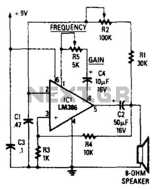
The circuit's frequency oscillation is given by the formula f = 2.8 / [Cix(i1 + i2)]. By utilizing the specified values, the output frequency can be adjusted from 60 Hz to 20 kHz by rotating potentiometer R2. A portion...
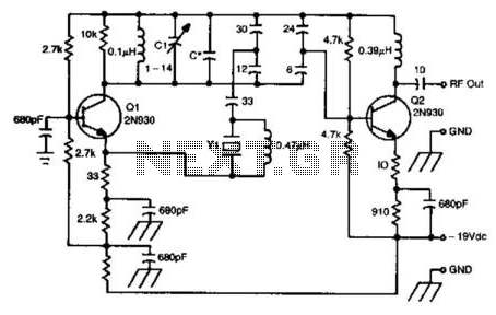
This oscillator circuit utilizes a 5th overtone crystal operating within the 85 to 106 MHz frequency range. The component Y1 represents the crystal. The circuit was initially designed for frequency control in a microwave oscillator. The oscillator circuit leveraging a...
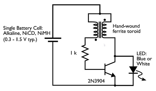
A transformer with two input leads and three output leads was used. An LED was connected to two of the output leads, and when a dead AA battery was connected to the input leads, the LED blinked for a...
This circuit operates at a frequency range of 30-200 parts per million (ppm) above the series resonance. It is physically simple, yet analytically complex. Additionally, it is cost-effective and exhibits reasonable frequency stability. The described circuit functions within a specific...