
Crystal Oscillators
The outlined circuit utilizes a crystal oscillator as a frequency source, which is fundamental in various electronic applications, particularly in timing and clock generation. The CD4040 counter IC is central to the design, providing a robust method for frequency division. The choice of a crystal frequency that is an even multiple of 2 simplifies the design by allowing automatic toggling of the counter stages, which is critical for generating a precise one-second pulse without additional complexity.
When employing a 32.768 kHz crystal, the circuit configuration must ensure that the output waveform is clean and stable, which is crucial for accurate timing applications. The use of the 4069 inverter is recommended due to its ability to produce a better square wave compared to alternative methods, such as a simple transistor circuit, which may introduce distortion or noise into the signal.
In applications requiring infrared communication, the 40 kHz oscillator circuit serves as an effective means to generate modulated light signals for testing purposes. The ability to drive an LED with substantial current pulses ensures adequate signal strength for reliable communication.
For engineers needing to verify quartz crystal performance, the described circuit provides a practical solution for testing crystals within the 10 kHz to 500 kHz range, addressing a common challenge faced in RF engineering.
The Pierce oscillator's design emphasizes the importance of feedback and stability in oscillator circuits, with the Barkhausen criteria serving as a guideline for ensuring sustained oscillation. This design is particularly relevant for applications that require precise frequency generation.
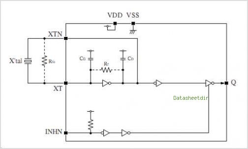
The ultra-low power and gated crystal oscillator circuits are ideal for battery-operated devices, where minimizing power consumption is essential. By employing a gating mechanism, these circuits can operate efficiently, providing necessary clock signals only when required while maintaining extremely low power draw during standby periods. This feature is particularly valuable in applications such as wearable technology and remote sensors, where battery life is a critical consideration.The schematic above illustrates dividing a crystal oscillator signal by the crystal frequency to obtain an accurate (0. 01%) 1 second time base. Two cascaded 12 stage counters (CD4040) form a 24 stage binary counter and the appropriate bits are gated together to produce the desired division.
Using a crystal of some even multiple of 2 is desirable so that one stage of the counter automatically toggles every second which eliminates the need for the NAND gate and reset circuitry, however the circuit below illustrates using a crystal which is not an even multiple of 2 and so requires additional. (electronic circuit) 32. 768 kHz Oscillator using a Common Watch Crystal - Below are a couple circuits you can use to produce a 32.
768 KHz square wave from a common watch crystal. The output can be fed to a 15 stage binary counter to obtain a 1 second square wave. The circuit on the left using the 4069 inverter is recommended over the transistor circuit and produces a better waveform. The single transistor circuit. (electronic diagram) 40kHz LED Test Signal Generator - This 40KHz crystal controlled oscillator circuit drives an infrared LED with powerful 40ma pulses.
The circuit can be used to test optical communications circuits, designed to receive 40KHz modulated light signals. . (designed by David A. Johnson) Crystal Controlled Oscillator (Ramon Vargas) - The RF engineer sometimes has to look for an instrument that will check a low frequency quartz crystal unit reliably and rapidly.
This is a difficult piece of equipment to find and the engineer often has to consult an electronic circuits handbook for the schematic of a circuit that will perform the task. Unfortunately, there aren`t many such circuits in the technical literature currently available, and when found, they don`t always work as expected.
A circuit that has been found to work at full satisfaction in the frequency range from 10 kHz to 500 kHz is illustrated in Figure 1. Crystal Oscillator (Chrontel) - Chrontel Application Note-06, This application note addresses issues commonly raised during the selection of the reference crystal, typically 14.
318 MHz, for Chrontel`s product line Crystal Oscillator (Goran Olsson) - ASCII format, The world is full of xtal oscillators twiddled by digital designers lacking in the analog design knowledge necessary. Just look at all the PC real time clocks that lags or leads by several minutes per day. And they eat backup batteries too! IC`s with pins that say "Xtal here" can`t be trusted either!. Pierce Crystal Oscillator Design - The Pierce oscillator. is essentially a common emitter amplifier with a tuned circuit for a collector load and a quartz crystal as a feedback element.
In order to determine whether the Barkhausen criteria is satisfied, loop gain must be determined at the frequency of oscillation. This is accomplished by drawing the AC equivalent circuit of the Pierce Oscillator. Ultra Low Power 32kHz Crystal Oscillator - I have used this circuit many times when I needed a low frequency reference, which did not draw much power.
With the components show, the current from a 3v battery is less than 1. 2 microamps. (designed by David A. Johnson) Very Low Power Gated Crystal Oscillator - The circuit gates the output of a continuously operating 32KHz crystal oscillator to the input of a C-MOS buffer when clock pulses are needed. The technique gets around the problem of a slow starting crystal oscillator by keeping the oscillator going and switching on a transistor power stage only as needed.
The method keeps the standby power consumption to a very low 1uA when used with a 3v supply. . (designed by David A. Johnson) XTAL-Controlled FM TX (V6) - My FM Wireless microphone V5 has been very popular, both as a beginners project and as a kit. It is interesting that it has also been the biggest cause of lots of e-mail, the most common questio 🔗 External reference
Related Circuits

This design schematic illustrates a Crystal Colpitts oscillator that can be implemented using a transistor and a parallel mode crystal. In this circuit, the crystal functions as an inductance. A large value capacitive divider is utilized between the gate,...
The CF8223A is an FSK (Frequency Shift Keying) decoder and DTMF (Dual Tone Multi-Frequency) receiver integrated circuit (IC). It is manufactured using a CMOS process and includes a power-down feature for low power dissipation operation. The FSK decoder and...
The 27MHz quartz crystal oscillator circuit is illustrated in figure 1. The biasing circuit consists of resistors R1, R2, and R3, while C6 serves as the bypass capacitor. The partial voltage circuit includes capacitors C1, C2, C3, and C4...
This article explains the specifications and characteristics of crystals and crystal oscillators, and aids in specifying crystals and working with crystal vendors. The article covers the significant performance characteristics of crystals, which include resonance frequency, resonance mode, load capacitance,...
Using a 50 Khz crystal, a count of 50000 is detected when the appropriate counter bits that add up to 50000 are all high. This corresponds to bits 15 (32768) + 14 (16384) + 9 (512) + 8 (256)...
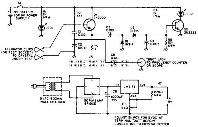
Q1 functions as a Colpitts crystal oscillator. If the crystal being tested is operational, the RF signal is rectified by diodes D1 and D2, which activates Q2 and illuminates indicator LED2. Additionally, LED1 serves as a power indicator. The circuit...
Warning: include(partials/cookie-banner.php): Failed to open stream: Permission denied in /var/www/html/nextgr/view-circuit.php on line 713
Warning: include(): Failed opening 'partials/cookie-banner.php' for inclusion (include_path='.:/usr/share/php') in /var/www/html/nextgr/view-circuit.php on line 713