
Antenna Input & Audio Lineout Adaptor For Portable Radios
The proposed adapter circuit effectively addresses the common challenges faced when connecting portable FM radios or MP3 players to external audio systems and antennas. By utilizing a radio-frequency choke, the circuit design ensures that audio signals are properly grounded while maintaining a clear path for the antenna signal. The use of capacitors to block low-frequency noise further enhances the overall performance, making this adapter a practical solution for users experiencing interference and audio quality issues. The compact design and straightforward assembly process make it accessible for hobbyists and engineers alike, providing a cost-effective means to improve the functionality of portable FM radios in various environments. This approach highlights the importance of careful consideration of grounding and signal paths in audio and radio frequency applications, ensuring optimal performance in real-world scenarios.Here is an idea for a simple low-cost adaptor that allows a portable FM radio (or MP3 player with FM tuner) to be connected to an external antenna and to audio equipment such as a hifi system or PC sound card. Portable FM radios and some MP3 players typically provide a 3. 5mm stereo jack socket for the headphone connection, with the shield conducto r of the headphone cable doubling as an antenna. Recently, the author bought a cheap FM radio with a USB connector, designed to be operated with a PC. The package included an audio cable with a 3. 5mm stereo phone plug at each end. The plug that goes into the radio has an additional wire (about 2m long) hanging out of it, which is meant to serve as an indoor antenna.
When using the supplied cable, the system suffered from poor radio reception (too much interference), and poor audio quality (lack of bass). The first problem was easily explained, as the radio was used in a marginal TV/FM reception area. When the cable was "buzzed out", the reason for the second problem became apparent. There was no audio ground connection, as the cable screen is not connected to anything at the radio end!
As mentioned, the antenna wire in these units is connected to the "common" terminal of the 3. 5mm socket, which normally doubles as the audio signal return path. If this terminal were to be connected to the ground of external audio equipment, the antenna signal would be clobbered. Perhaps the designer of this cable assumed that an adequate audio ground connection would be made indirectly via the USB cable a poor assumption!
The challenge then was to provide a good antenna signal for the radio while at the same time making a good audio ground connection to external equipment. Preferably, this was to be achieved without relying on the USB connector (because not all FM radios have one) and without having to mess with the radio`s internal works.
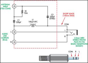
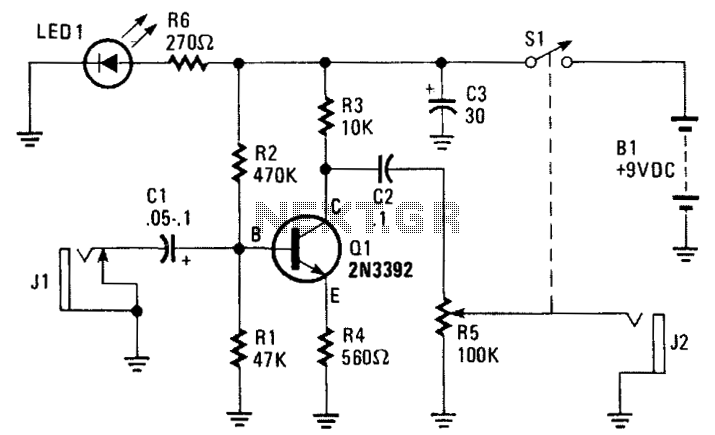
The accompanying circuit diagram shows how this can be achieved. The radio-frequency choke (L1) has a low impedance at audio frequencies, thereby making an audio ground path to the line output sockets from the radio`s antenna input ("common" terminal). Conversely, the RFC presents a high impedance to the RF antenna signal, so preventing it from being shorted to ground.
The antenna signal is coupled to the radio via two 220pF polystyrene (or ceramic) capacitors, which also block low-frequency interference (eg, mains hum). Note that the design relies on the capacitance in the audio cable to couple the antenna "ground" (cable shield) to the radio`s internal "ground".
To build the adaptor, simply mount the parts in a small plastic box and wire up as shown. A suitable choke is available from Jaycar (Cat. No. LF-1534). The leads going to the 3. 5mm plug should be no longer than about 100mm and need not be shielded. With a good TV/FM antenna, the author`s unit performed remarkably well, even in a poor FM reception area. The audio frequency response and signal-to-noise ratio were surprisingly good considering the low cost of the radio (about $40).
🔗 External reference
Related Circuits
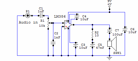
Here is a simple audio amplifier circuit that is easy to build and has few components. This circuit is built around the LM386 audio amplifier integrated circuit, useful when you need to power medium-sized speakers from a music player...
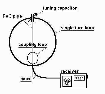
The small single turn magnetic loop (SSTML) antenna consists of a single winding inductor, about 3 feet (1 meter) in diameter, and a tuning capacitor. A second loop, which is one fifth of the diameter of the large loop,...
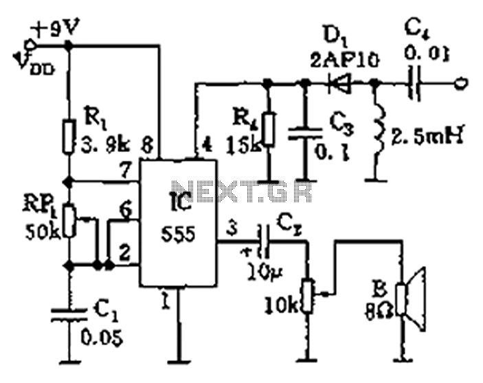
The circuit features a 555 timer integrated circuit along with components R1, RP1, C1, and others, which together form an audio oscillator. The frequency of the oscillator is determined by the formula f = 1.44 / ((R1 + 2...
The amplifier's gain is nominally 20 dB. Its frequency response is determined primarily by the values of a few components, mainly C1 and R1. The schematic diagram values provide a response of ±3.0 dB from approximately 120 Hz to...
In some cases, a cogwheel input is necessary for voltage measurement. By utilizing a single operational amplifier, an adapter can be created to accommodate a differential input for a ground-referenced voltmeter. It is recommended to use 1% tolerance metal...
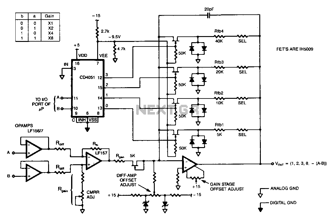
This programmable gain circuit utilizes a CD4051 CMOS Analog Multiplexer as a two to four line decoder, featuring appropriate FET drive for switching between feedback resistors to set the gain to one of four selectable values. The described programmable gain...
Warning: include(partials/cookie-banner.php): Failed to open stream: Permission denied in /var/www/html/nextgr/view-circuit.php on line 713
Warning: include(): Failed opening 'partials/cookie-banner.php' for inclusion (include_path='.:/usr/share/php') in /var/www/html/nextgr/view-circuit.php on line 713