
Audio booster

The amplifier circuit under discussion is designed to achieve a nominal gain of 20 dB, which is a standard level for audio amplification. The frequency response is critically influenced by the values of the components C1 and R1, which are integral to establishing the operational bandwidth of the amplifier. The specified frequency response of ±3.0 dB indicates that the amplifier will maintain its performance within this range, effectively covering audio frequencies from around 120 Hz to 20 kHz.
The flat frequency response from about 170 Hz to over 20 kHz suggests that the amplifier is well-suited for applications requiring high fidelity, such as in audio processing or musical instrument amplification. However, attention must be paid to the low-end response, as it begins to roll off below 170 Hz. This roll-off is primarily dictated by the capacitance of C1, as R1 remains constant, thus establishing a predictable low-frequency behavior.
In scenarios where further low-end extension is desired, adjusting the capacitance of C1 can significantly impact the performance. For instance, reducing C1 to 0.1 pF lowers the corner frequency to approximately 70 Hz, enhancing the amplifier's ability to reproduce lower frequencies. Additionally, if a more substantial low-end roll-off is necessary, substituting C1 with a 1.0 µF electrolytic capacitor is recommended. It is crucial to install this capacitor with the correct polarity to prevent damage and ensure proper circuit functionality; the positive terminal must connect to the base terminal of Q1, which is likely a transistor pivotal for the amplifier's operation.
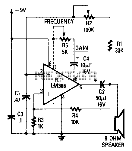
This circuit's design considerations highlight the importance of component selection and configuration in achieving desired audio characteristics, making it essential for engineers to understand the implications of each component's value on the overall performance of the amplifier.The amplifier's gain is nominally 20 dB. Its frequency response is determined primarily by the value of just a few components—primarily Cl and Rl. The values of the schematic diagram provide a response of ±3.0 dB from about 120 Hz to better than 20,000 Hz.
Actually, the frequency response is ruler flat from about 170 Hz to well over 20,000 Hz; it's the low end that deviates from a flat frequency response. The low end's roll-off is primarily a function of capacitor Cl (since Rl's resistive value is fixed).
If Cl's value is changed to 0.1 pF, the low end's corner frequency—the frequency at which the low-end roll-off starts—is reduced to about 70 Hz. If you need an even deeper low-end roll-off, change Cl to a 1.0 µ¥ capacitor; if it's an electrolytic type, make certain that it's installed into the circuit with the correct polarity, with the positive terminal connected to Ql's base terminal.
Related Circuits
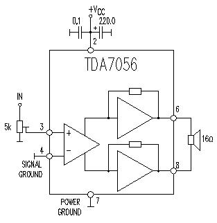
This TDA7056 power audio amplifier circuit diagram project is designed to deliver a maximum output power of 1 watt into an 8-ohm load when powered by a 6-volt supply, or a maximum output power of 3 watts into a...
I designed this circuit for one friend of mine to be used as a small portable DJ mixer. The circuit is an audio mixer circuit so simple as it can be. There are two dual logarithmic potentiometers in the...
The example below illustrates the use of an operational amplifier (op-amp) as an audio amplifier in a basic intercom system. A small 8-ohm speaker is utilized as a microphone, which is connected to the op-amp input through a 0.1...
The circuit's frequency of oscillation is given by the formula: f = 2.8 / [C1 x (R1 + R2)]. By adjusting the potentiometer R2, the output frequency can be varied from 60 Hz to 20 kHz. A portion of...
The external audio spectrum display circuit is designed for high-end audio equipment, providing both real-time playback signal analysis and visually appealing effects. This display does not require any electrical connections to the sound equipment; it can simply be placed...
This simple circuit mixes two or more channels into one channel (eg. stereo into mono). The circuit can mix as many or as few channels as you like and consumes very little power. The mixer is shown with two...