
12V Inverter Circuit Using 4013
The 12V inverter circuit employs a 555 timer integrated circuit (IC) in an astable mode to generate a square wave output. This output is essential for driving a power transistor or MOSFET that switches the current through a transformer, allowing for the conversion of 12V DC to a higher AC voltage. The frequency of the output waveform is crucial as it determines the efficiency and effectiveness of the inverter. The adjustable frequency feature allows users to fine-tune the output to match specific requirements or to optimize performance for different load conditions.
The circuit typically includes a few passive components such as resistors and capacitors, which set the timing characteristics of the 555 timer. The choice of these components directly influences the frequency and duty cycle of the output waveform. Additionally, a transformer is used to step up the voltage from the low-voltage side to a higher AC voltage suitable for powering devices.
To ensure reliable operation, the circuit should incorporate appropriate filtering and protection mechanisms. This may include diodes for flyback protection, capacitors for smoothing the output, and possibly a heat sink for the power transistor to manage thermal issues.
Overall, this 12V inverter circuit is an excellent project for electronics enthusiasts, providing a practical application of fundamental electronic principles while demonstrating the versatility of the 555 timer IC.This circuit is a circuit diagram 12V inverter is very easy to build, cheap components that many electronics hobbyists may even already have. Though it is possible to build a more powerful circuit, the complexity caused by the very heavy currents to be handled on the low-voltage side leads to circuits.
The circuit diagram of 12v inverter is easy to follow. A classic 555 timer chip, identified as IC1, is configured as an astable multivibrator at a frequency close to 100 Hz, which can be adjusted. 🔗 External reference
Related Circuits
Low-cost water pump controller circuit. The sensors used in the circuit can be any two conductive probes, preferably resistant to electrolytic corrosion. For example, a suitably sealed audio jack can be employed as the sensor. The automatic pump controller...
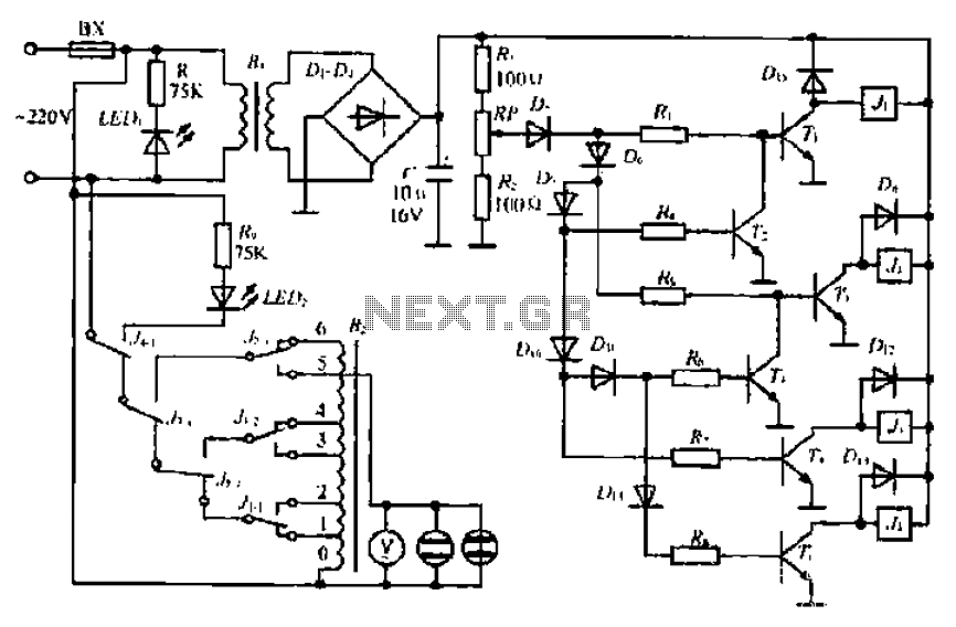
A step-down transformer converts AC 220V to a lower voltage. A diode bridge rectifier and filter capacitor provide a direct current (DC) output, which fluctuates with variations in the grid voltage. A resistive voltage divider is used for sampling....
At this voltage regulator prototype the maximum current, with output shortcircuited it was only 0.5 A, so no overheating occurred. In this DC voltage regulator circuit, T1 is for current limitation. As soon as the voltage on the R2...
This 24V to 36V linear battery charger is long overdue. While this is an old circuit technique, it is optimized for charging higher voltage lead-acid batteries. The 24V to 36V linear battery charger is designed to provide a stable charging...
This circuit diagram illustrates a triangular wave generating circuit utilizing a pair of operational amplifiers (Op-Amps). The LM741 Op-Amp is recommended for this application. The first Op-Amp, located on the left, functions as a comparator, while the second Op-Amp...
An FM transmitter circuit that utilizes a low power configuration, employing an operational amplifier as an audio preamplifier and a single transistor to function as the RF amplifier. This FM transmitter circuit is designed for low power applications, making...